Audio crossover
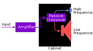
In a typical application, the signals sent to the surround speaker cabinets are further split up using a passive crossover into a low/mid-range woofer and a high-range tweeter.
Digital active crossovers often include additional signal processing, such as limiting, delay, and equalization.
If the separate bands are to be mixed back together again (as in multiband processing), then the ideal audio crossover would split the incoming audio signal into separate bands that do not overlap or interact and which result in an output signal unchanged in frequency, relative levels, and phase response.
Satisfactory output of the complete system comprising the audio crossover and the loudspeaker drivers in their enclosure(s) is the design goal.
A 3-way crossover is constructed as a combination of low-pass, band-pass and high-pass filters (LPF, BPF and HPF respectively).
4 (or more) way crossovers are not very common in speaker design, primarily due to the complexity involved, which is not generally justified by better acoustic performance.
An extra HPF section may be present in an "N-way" loudspeaker crossover to protect the lowest-frequency driver from frequencies lower than it can safely handle.
Ideal crossover filters, including impedance compensation and equalization networks, can be very difficult to design, as the components interact in complex ways.
IIR filters, which are by nature recursive, have the drawback that, if not carefully designed, they may enter limit cycles, resulting in non-linear distortion.
As with whizzer cones, careful selection of material, shape and position are required to provide smooth, extended output.
Cone profiles and materials can be modeled using finite element analysis software and the results are predicted to excellent tolerances.
Speakers which use these mechanical crossovers have some advantages in sound quality despite the difficulties of designing and manufacturing them and despite the inevitable output limitations.
Full-range drivers have a single acoustic center and can have relatively modest phase change across the audio spectrum.
Their small size (typically 165 to 200 mm) requires considerable cone excursion to reproduce bass effectively.
Higher orders are not generally implemented in passive crossovers for loudspeakers but are sometimes found in electronic equipment under circumstances for which their considerable cost and complexity can be justified.
This is because this filter type is 'transient perfect', meaning that the sum of the low-pass and high-pass outputs passes both amplitude and phase unchanged across the range of interest.
A first-order crossover allows more signal content consisting of unwanted frequencies to get through in the LPF and HPF sections than do higher-order configurations.
In practice, speaker systems with true first-order acoustic slopes are difficult to design because they require large overlapping driver bandwidth, and the shallow slopes mean that non-coincident drivers interfere over a wide frequency range and cause large response shifts off-axis.
This order is commonly used in passive crossovers as it offers a reasonable balance between complexity, response, and higher-frequency driver protection.
And so, in a 2-way system, the high-pass section's output is usually connected to the high-frequency driver 'inverted', to correct for this phase problem.
For passive systems, the tweeter is wired with opposite polarity to the woofer; for active crossovers the high-pass filter's output is inverted.
Such steep-slope filters have greater problems with overshoot and ringing[16] but there are several key advantages, even in their passive form, such as the potential for a lower crossover point and increased power handling for tweeters, together with less overlap between drivers, dramatically reducing the shifting of the main lobe of a multi-way loudspeaker system's radiation pattern with frequency,[7] or other unwelcome off-axis effects.
With less frequency overlap between adjacent drivers, their geometric location relative to each other becomes less critical and allows more latitude in speaker system cosmetics or (in-car audio) practical installation constraints.
Their two outputs maintain a constant zero-phase difference across the transition, thus enhancing their lobing performance with noncoincident loudspeaker drivers.
Parallel crossovers also have the advantage of allowing the speaker drivers to be bi-wired, a feature whose benefits are hotly disputed.
A low-frequency signal with a similar instantaneous voltage characteristic first passes through the LPF, then the woofer, and appears at the lower Input terminal.
The main advantage of derived filters is that they produce no phase difference between the high-pass and low-pass sections at any frequency.
This requires the speaker to which it is directed to continue to respond to signals deep into the stopband where its physical characteristics may not be ideal.
In the case of (2), above, both speakers are required to operate at higher volume levels as the signal nears the crossover points.
In the period before computer modeling made it affordable and quick to simulate the combined effects of drivers, crossovers and cabinets, a number of issues could go unnoticed by the speaker designer.