Railway air brake
[1] Modern trains rely upon a fail-safe air brake system that is based upon a design patented by George Westinghouse on April 13, 1869.
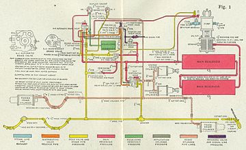
The mechanical linkage can become quite elaborate, as it evenly distributes force from one pressurized air cylinder to 8 or 12 wheels.
In so doing, it supports certain other actions (i.e. it 'holds' or maintains the application and it permits the exhaust of brake cylinder pressure and the recharging of the reservoir during the release).
The speed of pressure changes during a service reduction is limited by the compressed air's ability to overcome the flow resistance of the relatively-small-diameter pipe and numerous elbows throughout the length of the train, and the relatively-small exhaust port on the head-end locomotive, which means the brakes of the rear-most cars will apply sometime after those of the forward-most cars apply, so some slack run-in can be expected.
The locomotive(s) at the head of the train (the "lead consist") have a secondary system called the independent brake.
An emergency application also results when the integrity of the brake pipe is lost, as all air will also be immediately vented to atmosphere.
The emergency portion of each triple valve is activated by the higher rate of reduction of brake pipe pressure.[how?]
This serves to more rapidly vent the brake pipe and hasten the propagation of the emergency reduction rate along the entire length of the train.
Use of distributed power (i.e., remotely controlled locomotive units mid-train and/or at the rear end) somewhat mitigates the time-lag problem with long trains, because a telemetered radio signal from the engine operator in the front locomotive commands the distant units to initiate brake pressure reductions that propagate quickly through nearby cars.
As of 2005[update], electro-pneumatic brakes were in testing in North America and South Africa on captive service ore and coal trains.
This controller compared the pressure in the straight air trainline with that supplied by a self-lapping portion of the engineers valve, signaling all of the "apply" or "release" magnets valves in the train to open simultaneously, changing the pressure in the straight-air trainline much more rapidly and evenly than possible by simply supplying air directly from the locomotive.
The relay valve was equipped with four diaphragms, magnet valves, electric control equipment, and an axle-mounted speed sensor, so that at speeds over 60 mph (97 km/h) full braking force was applied, and reduced in steps at 60, 40 and 20 mph (97, 64 and 32 km/h), bringing the train to a gentle stop.
The straight-air (electro-pneumatic trainline), anti-lock, and speed graduating portions of the system were not dependent on each other in any way, and any or all of these options could be supplied separately.
However, if the brake pipe pressure is too low due to an excessive number of brake applications, an emergency application will not produce a large enough volume of air flow to trip the triple valves, leaving the engine driver with no means to stop the train.
Care would then be given when releasing the service and dynamic brakes to prevent draw-gear damage caused by a sudden run out of the train's slack.
Another solution to loss of brake pressure is the two-pipe system, fitted on most locomotive-hauled passenger stock and many freight wagons.
These valves cut off the air from the train line and vent the coupling hoses for uncoupling cars.
The air brake only operates if the angle cocks are open except the ones at the front of the locomotive and at the end of the train.
Similarly, in the Gare de Lyon rail accident, a valve was accidentally closed by the crew, reducing braking power.
Railroads have strict government-approved procedures for testing the air brake systems when making up trains in a yard or picking up cars en route.
An example of this problem can be seen in the accident that caused the death of John Luther "Casey" Jones on 30 April 1900 on the Illinois Central Railroad main line at Vaughan, Mississippi.
European passenger cars used on national railway networks must comply with TSI LOC&PAS regulation,[12] which specifies in section 4.2.4.3 that all brake systems must adhere to the EN 14198:2004 standard.
Some locomotives, e.g. on the London, Brighton and South Coast Railway, were dual-fitted so that they could work with either vacuum- or air-braked trains.
In the diesel era, the process was reversed and British Railways switched from vacuum-braked to air-braked rolling stock in the 1960s.
Disconnection taps at the ends of cars are not required because the loose hoses are sucked onto a mounting block.
Electro-vacuum brakes have been used with considerable success on South African electric multiple unit trains.