Aluminum electrolytic capacitor
A non-solid electrolyte covers the rough surface of the oxide layer, serving in principle as the second electrode (cathode) (-) of the capacitor.
However, it can evaporate through a temperature-dependent drying-out process, which causes electrical parameters to drift, limiting the service life time of the capacitors.
The exception is the bipolar or non-polar aluminum electrolytic capacitor, which has a back-to-back configuration of two anodes in a single case, and which can be safely used in AC applications.
The dielectric thickness of electrolytic capacitors is very thin, in the range of nanometers per volt, but the voltage strengths of these oxide layers are quite high.
An electrically insulating oxide layer Al2O3 is thereby formed on the aluminum surface by application of a current in correct polarity if it is inserted in an electrolytic bath.
[3] The disadvantage of crystalline oxide is its greater sensitivity to tensile stress, which may lead to microcracks when subjected to mechanical (winding) or thermal (soldering) stressors during the post-forming processes.
In order to reduce the contact resistance to the electrolyte and to make it difficult for oxide formation during discharging, the cathode foil is alloyed with metals such as copper, silicon, or titanium.
In case of a malfunction, overload or wrong polarity operating inside the electrolytic capacitor housing, substantial gas pressure can arise.
[11][12] The foils are fed to an automatic winder, which makes a wound section in a consecutive operation involving three sequential steps: terminal welding, winding, and length cutting.
This optically ready capacitor is then contacted at rated voltage in a high temperature post-forming device for healing all the dielectric defects resulting from the cutting and winding procedure.
Karol Pollak, a producer of accumulators, found out that the oxide layer on an aluminum anode remained stable in a neutral or alkaline electrolyte, even when the power was switched off.
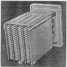
The first common application of wet aluminum electrolytic capacitors was in large telephone exchanges, to reduce relay hash (noise) on the 48 volt DC power supply.
The development of AC-operated domestic radio receivers in the late 1920s created a demand for large-capacitance (for the time) and high-voltage capacitors for the valve amplifier technique, typically at least 4 microfarads and rated at around 500 volts DC.
Waxed paper and oiled silk film capacitors were available, but devices with that order of capacitance and voltage rating were bulky and prohibitively expensive.
The ancestor of the modern electrolytic capacitor was patented by Samuel Ruben in 1925,[23][24] who teamed with Philip Mallory, the founder of the battery company that is now known as Duracell International.
The period after World War II is associated with a rapid development in radio and television technology as well as in industrial applications, which had great influence on production quantities but also on styles, sizes and series diversification of electrolytic capacitors.
[31] The decades from 1970 to 1990 were marked by the development of various new professional aluminum electrolytic capacitor series with f. e. very low leakage currents or with long life characteristics or for higher temperatures up to 125 °C, which were specifically suited to certain industrial applications.
These capacitors use as solid organic conductor the charge transfer salt TTF-TCNQ (tetracyanoquinodimethane), which provided an improvement in conductivity by a factor of 10 with respect to the manganese dioxide electrolyte.
Due to their large capacitance values, aluminum electrolytic capacitors have relatively good decoupling properties in the lower frequency range up to about 1 MHz or a little more.
[42] Non-solid aluminum electrolytic capacitors that leakage current after an operation time of, for example, one hour remain on a higher level than specified.
For other conditions of applied voltage, current load, temperature, capacitance value, circuit resistance (for tantalum capacitors), mechanical influences and humidity the FIT figure can recalculated with acceleration factors standardized for industrial[49] or military[50] contexts.
In response to demands for long life, high temperature performance from automotive and green energy applications (solar microvinverters, LEDs, wind turbines, etc.
But the additional internal heat of 3 to 10 K, depending on the series, which is generated by the ripple current is usually taken into account by the manufacturer due to safety margins when interpreting the results of its endurance tests.
They use different ways achieve the specification; some provide special formulas,[55][56][57] others specify their capacitor lifetime calculation with graphs that take into account the influence of applied voltage.
With today's high levels of purity in the manufacture of electrolytic capacitors it is not to be expected that short circuits occur after the end-of-life-point with progressive evaporation combined with parameter degradation.
This leads in turn to a previously unnoticed water driven corrosion, which weakens the stable dielectric oxide layer during storage or disuse.
Their advantages, among other things were lower leakage currents and nearly unlimited shelf life,[70] but this led to another problem: the growing mass production with automatic insertion machines requires a washing of the PCB's after soldering; these cleaning solutions contained chloroalkane (CFC) agents.
In the meantime electrolytic systems have been developed with additives to inhibit the reaction between anodic aluminum oxide and water, which solve most of the high leakage current problems after storage.
Nearly all today's series of capacitors fulfill the 1000 hours shelf life test, which is equivalent to a minimum five years of storage at room temperature.
Some applications like AC/AC converters with DC-link for frequency controls in three-phase grids need higher voltages than electrolytic capacitors usually offer.