American wire gauge
[1] The cross-sectional area of each gauge is an important factor for determining its current-carrying capacity.
The AWG originated in the number of drawing operations used to produce a given gauge of wire.
However, AWG is dissimilar to IEC 60228, the metric wire-size standard used in most parts of the world, based directly on the wire cross-section area (in square millimetres, mm2).
The AWG of a stranded wire is determined by the cross-sectional area of the equivalent solid conductor.
Because each successive gauge number increases cross sectional area by a constant multiple, diameters vary geometrically.
or equivalently: The gauge can be calculated from the diameter using [2] and the cross-section area is The standard ASTM B258-02 (2008), Standard Specification for Standard Nominal Diameters and Cross-Sectional Areas of AWG Sizes of Solid Round Wires Used as Electrical Conductors, defines the ratio between successive sizes to be the 39th root of 92, or approximately 1.1229322.
The sixth power of 39√92 is very close to 2,[4] which leads to the following rules of thumb: Convenient coincidences result in the following rules of thumb for resistances: The table below shows various data including both the resistance of the various wire gauges and the allowable current (ampacity) based on a copper conductor with plastic insulation.
Fusing current (melting wire) is estimated based on 25 °C (77 °F) ambient temperature.
The table below assumes DC, or AC frequencies equal to or less than 60 Hz, and does not take skin effect into account.
As indicated in the Formulas and Rules of Thumb sections above, differences in AWG translate directly into ratios of diameter or area.
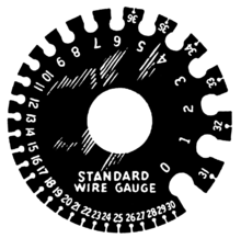
Such measurement can be done with a wire gauge go-no-go tool or with a caliper or micrometer.
Alternative ways are commonly used in the electrical industry to specify wire sizes as AWG.