CFM International CFM56
Research into the next generation of commercial jet engines, high-bypass ratio turbofans in the "10-ton" (20,000 lbf; 89 kN) thrust class, began in the late 1960s.
GE needed an engine in this market class, and Snecma had previous experience of working with them, collaborating on the production of the CF6-50 turbofan for the Airbus A300.
[4] Pratt & Whitney was considering upgrading their JT8D to compete in the same class as the CFM56 as a sole venture, while Rolls-Royce dealt with financial issues that precluded them from starting new projects; this situation caused GE to gain the title of best partner for the program.
The United States Department of State's Office of Munitions Control recommended the rejection of the application on national security grounds; specifically because the core technology was an aspect of a strategic national defense system (B-1 bomber), it was built with Department of Defense funding, and that exporting the technology to France would limit the number of American workers on the project.
Efforts continued throughout the months following the rejection, culminating in the engine becoming an agenda topic during the 1973 meeting of Presidents Nixon and Pompidou in Reykjavík.
Contemporary reports state that the agreement was based on assurances that the core of the engine, the part that GE was developing from the military F101, would be built in the U.S. and then transported to France in order to protect the sensitive technologies.
[3] Documents declassified in 2007 revealed that a key aspect of the CFM56 export agreement was that the French government agreed not to seek tariffs against American aircraft being imported into Europe.
[11] With the export issue settled, GE and Snecma finalized the agreement that formed CFM International (CFMI), a 50–50 joint company that would be responsible for producing and marketing the 10-ton engine, the CFM56.
[13] The two primary roles for CFMI were to manage the program between GE and Snecma, and to market, sell and service the engine at a single point of contact for the customer.
The main targets were re-engine contracts for the Douglas DC-8 and the Boeing 707 airliners, including the related military tanker, the KC-135 Stratotanker.
[27] In 1998, CFMI launched the "Tech56" development and demonstration program to create an engine for the new single-aisle aircraft that were expected to be built by Airbus and Boeing.
The program focused on developing a large number of new technologies for the theoretical future engine, not necessarily creating an all-new design.
[28][29] When it became clear that Boeing and Airbus were not going to build all-new aircraft to replace the 737 and A320, CFMI decided to apply some of those Tech56 technologies to the CFM56 in the form of the "Tech Insertion" program which focused on three areas: fuel efficiency, maintenance costs and emissions.
[38] Lufthansa, launch customer for the CFM56-5C-powered A340, have an engine with more than 100,000 flight hours, having entered commercial service on 16 November 1993, overhauled four times since.
Once restored, the life limited parts must be replaced after: 20,000 cycles for the hot section ($0.5m), 25,000 for the axial compressor, and 30,000 for the fan and booster ($0.5m-$0.7m) for a recent CFM56.
The new one was not fully replacing the old one, but it offered an upgrade in HPC, thanks to improved blade dynamics, as a part of their "Tech Insertion" management plan from 2007.
[nb 3][54] After examining configurations in the wind tunnel, CFMI chose to flight-test chevrons built into the core exhaust nozzle.
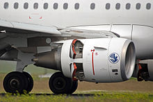
This type of thrust reverse consists of sleeves that slide back to expose mesh-like cascades and blocker doors that block the bypass air flow.
In some variants, the HPT blades are "grown" from a single crystal superalloy, giving them high strength and creep resistance.
It has three distinct sub-variants; the CFM56-5A, CFM56-5B and CFM56-5C,[3] and differs from its Boeing 737 Classic-fitted cousins by featuring a FADEC and incorporating further aerodynamic design improvements.
[67] Rated with a takeoff thrust range of 19,500–27,300 lbf (87–121 kN), it powers the -600/-700/-800/-900 Boeing 737 Next Generation; compared to the CFM56-3, it has greater durability, 8% fuel burn improvement and a 15% reduction in maintenance costs.
Less than two years after entry into service, the Next-Generation 737 received 180 minutes Extended range twin engine Operations (ETOPS) certification from the US Federal Aviation Administration (FAA).
It also powers the Boeing 737 military versions : Airborne Early Warning & Control, C-40 Clipper transport and P-8 Poseidon Maritime Aircraft.
[68] After the Southwest Airlines Flight 1380 accident, the FAA required Boeing to redesign the nacelle and inlet of the 7B variant in compliance with applicable Part 25 regulations.
In 1987, a double flameout occurred in hail conditions (the pilots managed to relight the engines), followed by the TACA Flight 110 incident in 1988.
The major changes included a modification to the fan/booster splitter (making it more difficult for hail to be ingested by the core of the engine) and the use of an elliptical, rather than conical, spinner at the intake.
These changes did not prevent the 2002 accident, and the investigation board found that the pilots did not follow the proper procedures for attempting to restart the engine, which contributed to the final result.
Recommendations were made to better educate pilots on how to handle these conditions, as well as to revisit FAA rain and hail testing procedures.
Following the Kegworth accident, CFM56 engines fitted to a Dan-Air 737-400 and a British Midland 737-400 suffered fan blade failures under similar conditions; neither incident resulted in a crash or injuries.
[79] In 2023, Bloomberg reported that European aviation regulators had determined that London-based AOG Technics, majority owned by Jose Zamora Yrala, whose nationality is listed as British on some forms and Venezuelan on others, supplied parts of unknown origin and false documents for repairs on some CFM56s.