Charlieplexing
A slight improvement is to have everything return on a common ground, but this still requires one wire (and one pin on the microcontroller) for each pixel or button.
Although it is more efficient in its use of I/O, a small amount of address manipulation is required when trying to fit Charlieplexing into a standard x/y array.
[6] It was named after Charles "Charlie" M. Allen, an applications engineer of MAX232 fame,[8][9][10] who had proposed this method internally.[when?]
Also in 2001, Don Lancaster illustrated the method as part of his musings about the "N-connectedness" problem,[11] referring to Microchip Technology,[11] who had already discussed it as "complementary LED drive technique" in a 1998 application note[12] and would later include it in a tips & tricks booklet.
[14][15] The method, however, was known and utilized by various parties much earlier in the 1980s, and has been described in detail as early as in 1979 in a patent by Christopher W. Malinowski, Heinz Rinderle and Martin Siegle of the Department of Research and Development, AEG-Telefunken, Heilbronn, Germany for what they called a "three-state signaling system".
[16] Reportedly, similar techniques were already in use as early as 1972 for track signaling applications in model railroading.
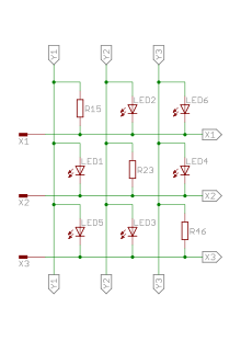
Six (n) conductive elements in a standard x/y multiplexed array forms a maximum of nine ((n / 2)2) unique intersections (see figure on far left).
The 6 unusable diagonal LEDs can be conveniently replaced by actual bidirectional shortcuts (so that there's no longer need to set up the interconnection lines grouped on the left and bottom of the diagrams, to drive the bottom input of vertical connectors from the matching left input of horizontal connectors).
Charlieplexing can also be used to significantly reduce the number of controlling pins for much larger matrixes, such as modern digital displays with high resolution.
But with Charlieplexing, this can be reduced to only 63 controlling pins for the selection gate of display columns, plus 46 × 3 controlling pins for the selection and power-activation of RGB display rows, by a single transistor for each row or column (possibly with an extra common shielding ground to limit their mutual coupling); these controlling pins can easily fit around the output pins of one or two controller chips, even if we add the few additional pins needed on the controller for power, ground, clocks and I/O buses, surface-mounted with a high density and low cost on a single-layer PCB, and no need of complex routing and interconnection holes between layers; a dual layer is needed only for the basic Charlieplexing matrix mounted on borders of the panel itself.
Positions in the Charlieplexed matrix are not reduced to be just LEDs or diodes, they can be filled as well by two pins of a transistor (including its gate pin) so that its third pin is used as output to further control other devices, such as the horizontal and vertical selection lines of a large flat display panel (in that case, the two Charlieplexed matrices of transistors controlling and activating the rows or columns of the panel will be smartly arranged all along a border of that panel).
Charlieplexing in its simplest form works by using a diode matrix of complementary pairs of LEDs.
Since current cannot flow through LEDs in reverse direction at this low voltage, LED2 will remain unlit.
In this two-LED example, Charlieplexing would save one ground wire, which would be needed in a common 2-pin driver situation.
However, in the variant with individual resistors this voltage-regulating effect does not affect the alternative paths so all LEDs used will not have to be lit with half the supply voltage applied because this variant does not benefit from the voltage-regulating effect of the desired path LED.
Under the same constraints as discussed above up to n − 1 LEDs sharing a common positive or negative path can be lit in parallel.
This emphasizes the similarities between ordinary grid multiplex and Charlieplex, and demonstrates the pattern that leads to "the n-squared minus n" rule.
In typical usage on a circuit board the resistors would be physically located at the top of the columns and connected to the input pin.
In both of these configuration, as shown in both the left and the right image, the relocated resistors make it possible to light multiple LEDs at the same time row-by-row, instead of requiring that they be lit individually.
But to show a desired number using all 8 digits, only one 7-segment display can be shown at a time, so all 8 must be cycled through separately, and in a 50th of a second for the entire period of 8.
Thus the display must be refreshed at 400 Hz for the period-8 cycle through all 8 segments to make the LEDs flash no slower than 50 times per second.
Since the current from microcontroller pins is typically limited to about 20 mA, this severely restricts the practical size of a Charlieplexed display.
To read whether a switch is open or closed, the microcontroller configures one pin as an input with an internal pull-up resistor.
(However, it is probably possible to arrange the circuit so that if at most any two adjacent buttons are pressed, then no data loss will occur.
These tracks can be made from a wide range of materials, such as printed circuit boards, transparent Indium Tin oxide, insulation coated fine wire, etc.
The technology can range in size from very small, as in "fingerprint detectors",[21] to very large, as in "touch interactive video walls".
Usually, a limit is imposed on the maximum width of an x/y wired touchscreen, because the horizontal track resistance gets too great for the product to function properly.
[28][29] Also, the analog & mixed signal (AMS)[nb 1] division (named Lumissil Microsystems since 2020) of Integrated Silicon Solution Inc. (ISSI) introduced the IS31FL3731 in 2012[30][31] and the IS31FL3732 in 2015.
[32][33][34] They all use a technique they call cross-plexing, a variant of Charlieplexing with automatic detection of open or shorted connections and anti-ghosting measures.
[35] In 2019, Micah Elizabeth Scott developed a method to use 3 pins to run 4 LEDs and 4 switches called Tucoplexing.