Class diagram
In software engineering, a class diagram[1] in the Unified Modeling Language (UML) is a type of static structure diagram that describes the structure of a system by showing the system's classes, their attributes, operations (or methods), and the relationships among objects.
The class diagram is the main building block of object-oriented modeling.
In detailed modeling, the classes of the conceptual design are often split into subclasses.
[4] UML provides mechanisms to represent class members, such as attributes and methods, and additional information about them like constructors.
A derived property is shown with its name preceded by a forward slash '/'.
[6] The UML specifies two types of scope for members: instance and class.
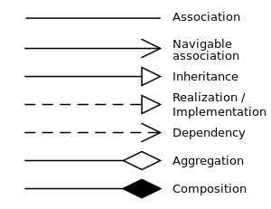
A relationship is a general term covering the specific types of logical connections found on class and object diagrams.
A dependency is displayed as a dashed line with an open arrow that points from the client to the supplier.
A unidirectional navigation is shown with a little cross on the association line on the side of the class that cannot be reached.
UML 2 does not specify any semantic for the aggregation compared to the simple association.
The UML graphical representation of a Realization is a hollow triangle shape on the interface end of the dashed line (or tree of lines) that connects it to one or more implementers.
A plain arrow head is used on the interface end of the dashed line that connects it to its users.
In component diagrams, the ball-and-socket graphic convention is used (implementors expose a ball or lollipop, whereas users show a socket).
This association relationship indicates that (at least) one of the two related classes make reference to the other.
For example, we can indicate, using an arrowhead that the pointy end is visible from the arrow tail.
We can indicate ownership by the placement of a ball, the role the elements of that end play by supplying a name for the role, and the multiplicity of instances of that entity (the range of number of objects that participate in the association from the perspective of the other end).