Coordinate-measuring machine
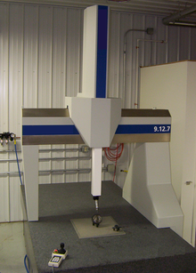
The typical 3D "bridge" CMM allows probe movement along three axes, X, Y, and Z, which are orthogonal to each other in a three-dimensional Cartesian coordinate system.
This process is repeated as necessary, moving the probe each time, to produce a "point cloud" which describes the surface areas of interest.
They can also be used to construct geometric features such as cylinders and planes for GD&T so that aspects like roundness, flatness, and perpendicularity can be assessed.
The first CMM was developed by the Ferranti Company of Scotland in the 1950s[1] as the result of a direct need to measure precision components in their military products, although this machine only had 2 axes.
The first 3-axis models began appearing in the 1960s (made by DEA of Italy and LK of the UK), and computer control debuted in the early 1970s, but the first working CMM was developed and put on sale by Browne & Sharpe in Melbourne, England.
The rotary table as a fourth drive axis does not enhance the measuring dimensions, which remain 3D, but it does provide a degree of flexibility.
In the early days of coordinate measurement, mechanical probes were fitted into a special holder on the end of the quill.
These probes were physically held against the workpiece with the position in space being read from a 3-axis digital readout (DRO) or, in more advanced systems, being logged into a computer by means of a footswitch or similar device.
Operators no longer had to physically touch the machine but could drive each axis using a handbox with joysticks in much the same way as with modern remote controlled cars.
Measurement accuracy and precision improved dramatically with the invention of the electronic touch trigger probe.
As the probe touched the surface of the component, the stylus deflected and simultaneously sent the X,Y,Z coordinate information to the computer.
Optical probes are lens-and-CCD systems, which are moved like the mechanical ones, and are aimed at the point of interest, instead of touching the material.
The captured image of the surface will be enclosed in the borders of a measuring window, until the residue is adequate to contrast between black and white zones.
Although these machines are good and in many cases excellent metrology platforms with nanometric scales, their primary limitation is a reliable, robust, capable micro/nano probe.
[citation needed] Challenges for microscale probing technologies include the need for a high-aspect-ratio probe giving the ability to access deep, narrow features with low contact forces so as to not damage the surface and high precision (nanometer level).
[citation needed] Additionally, microscale probes are susceptible to environmental conditions such as humidity and surface interactions such as stiction (caused by adhesion, meniscus, and/or Van der Waals forces among others).
Designed with compact linear or matrix array cameras (like the Microsoft Kinect), optical CMMs are smaller than portable CMMs with arms, feature no wires, and enable users to easily take 3D measurements of all types of objects located almost anywhere.
Certain nonrepetitive applications such as reverse engineering, rapid prototyping, and large-scale inspection of parts of all sizes are ideally suited for portable CMMs.