Course Setting Bomb Sight
It was introduced in 1917, and was such a great advance over earlier designs that it was quickly adopted by the Royal Flying Corps, and the Independent Air Force.
The primary pre-war device in RNAS service was the Lever Sight, which the pilot had to hold out of the cockpit in one hand while flying the aircraft with the other.
A gear in the knob that adjusted the rod angle also drove the sights fore or aft, moving them to account for the wind speed.
[1] His new Course Setting Bomb Sight featured a large compass at the rear that could be used for making general calculations of wind speed or solving navigational problems.
The Royal Flying Corps (RFC) started using the Mark I sight as soon as supplies were available, and by April 1918 were also fully converted to this type.
At higher altitudes or forward speeds the bombs would reach terminal long before impact, which had the effect of making the last portion of the flight path more vertical.
[9] Later versions used by RAF Coastal Command and the Royal Navy also included a further adjustment, the Fourth Vector, for attacking moving targets.
This was a fairly complex system of rotating rings and sliders that allowed the bomb aimer to dial in the relative course of the target and its estimated speed.
X replaced the vertical slider used for altitude adjustment with a horizontally-moving backsight at the top of the device, and the entire foresight and drift wire area was made considerably smaller.
The calculator and wind drift settings, formerly mounted on top and in front of the large compass at the rear of the earlier models, was moved to the left side of the device and changed in form to make it smaller as well.
The biplane bombers the CSBS had been developed for had the ability to slip-turn using the rudder only, which made it simple for the pilot to adjust their heading without affecting the aim too much.
[15] In the aftermath of the Wilhelmshaven raid on 3 September 1939, it was found that the lengthy setup and bomb run demanded by the CSBS made its aircraft extremely vulnerable to fighters and anti-aircraft artillery.
However, the large physical size of the CSBS series, especially the long drift bar, made it difficult to mount successfully on a platform.
XI, which mounted a single drift wire and iron sight on the front of a gyroscope taken from a Sperry artificial horizon that was already common in RAF use.
[17] As if these problems were not enough, the RAF found in the training schools that it was all too common for the bomb aimers to dial in an incorrect setting, or forget to update one when conditions changed.
The box contained the inputs needed to drive the vector calculator, as well as copies of the various aircraft instruments displaying the required information.
As the sighting head lacked the vector computer it was much smaller than earlier models, which allowed it to be easily mounted on a stabilized platform.
[16] It did not offer the level of accuracy of tachometric bombsights like the Norden or ABS, but for night area bombing from medium altitude as practiced by RAF Bomber Command this was not an issue.
[20] The bombsight problem is the need to determine the exact spot in the air where the bombs should be dropped to hit a target on the ground.
Due to the acceleration of gravity, bombs follow a roughly parabolic path, the steepness being defined by the forward speed of the aircraft at the instant of release.
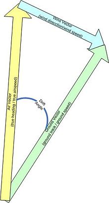
[21] Calculating the proper drift angle is a simple task of basic vector addition, and is commonly carried out on a circular slide rule like the E6B.
The top of the bearing plate was designed to be drawn on with a chinagraph pencil so it could serve as a general navigation calculator as well.
[26] Connected to and extending from the front of the main bombsight housing is the drift bar, normally forming over half the overall length of the device.
The length of this vector is set by the air speed drum, found on the right side of the main case (or at the back of the device on earlier versions).
Turning the air speed knob that pushes the tube carrying the wind direction shaft fore or aft.
In order to approach the target properly, the aircraft needs to turn to the left until the portion of its airspeed equal to the wind speed cancels out the drift.
The length of the yellow arrow is set by rotating the air speed drum, carrying the windage calculator with it.
[31] Once set, the bomb aimer uses the rear sights, or any other convenient part of the bombsight, as a reference location and spots past them through the drift wires.
When initially set up the aircraft would likely be flying a course close to the green arrow, so the bomb aimer would see the targets drifting to the left relative to the wires.
Next, the ground speed was measured by timing objects as they passed through any two sets of small beads on the main drift bar using a stopwatch.