Crossbar switch
Originally, a crossbar switch consisted literally of crossing metal bars that provided the input and output paths.
The matrix layout of a crossbar switch is also used in some semiconductor memory devices which enables the data transmission.
[3] At the 2008 NSTI Nanotechnology Conference a paper was presented that discussed a nanoscale crossbar implementation of an adding circuit used as an alternative to logic gates for computation.
Thin-film-transistor LCDs have a transistor at each crosspoint, so they could be considered to include a crossbar switch as part of their structure.
In a typical installation, all the video sources are located on an equipment rack, and are connected as inputs to the matrix switch.
Ordinarily, a sports bar would install a separate desk top box for each display for which independent control is desired.
Video sources typically shared include set-top receivers or DVD changers; the same concept applies to audio.
The actual user interface varies by system brand, and might include a combination of on-screen menus, touch-screens, and handheld remote controls.
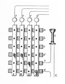
Historically, a crossbar switch consisted of metal bars associated with each input and output, together with some means of controlling movable contacts at each cross-point.
An important emerging class of optical crossbars is implemented with microelectromechanical systems (MEMS) technology.
A type of mid-20th-century telegraph exchange consisted of a grid of vertical and horizontal brass bars with a hole at each intersection (c.f.
The first design of what is now called a crossbar switch was the Bell company Western Electric's coordinate selector of 1915.
In 1945, a similar design by Swedish Televerket was installed in Sweden, making it possible to increase the capacity of the A204 model switch.
In the early 1960s, the company's sales of crossbar switches exceeded those of their rotating 500-switching system, as measured in the number of lines.
Crossbar switching quickly spread to the rest of the world, replacing most earlier designs like the Strowger (step-by-step) and Panel systems in larger installations in the U.S. Graduating from entirely electromechanical control on introduction, they were gradually elaborated to have full electronic control and a variety of calling features including short-code and speed-dialing.
The majority of Bell System switches were made to connect three wires including the tip and ring of a balanced pair circuit and a sleeve lead for control.
The Bell System Type C miniature crossbar of the 1970s was similar, but the fingers projected forward from the back and the select bars held paddles to move them.
The sender then recorded the dialed digits and passed them to the originating marker, which selected an outgoing trunk and operated the various crossbar switch stages to connect the calling user to it.
The crossbar switch itself was simple: exchange design moved all the logical decision-making to the common control elements, which were very reliable as relay sets.
The design criteria specified only two hours of downtime for service every forty years, which was a large improvement over earlier electromechanical systems.
In control occupancy terms this comparatively long interval degrades the traffic capacity of a switch.
The only downside of common control was the need to provide digit recorders enough to deal with the greatest forecast originating traffic level on the exchange.
The Plessey TXK1 or 5005 design used an intermediate form, in which a clear path was marked through the switching fabric by distributed logic, and then closed through all at once.
[citation needed] In the classic telephony application of crossbars, the crosspoints are closed, and open as the telephone calls come and go.
In Asynchronous Transfer Mode or packet switching applications, the crosspoints must be made and broken at each decision interval.