Registered jack
Registered interfaces were first defined in the Universal Service Ordering Code (USOC) of the Bell System in the United States for complying with the registration program for customer-supplied telephone equipment mandated by the Federal Communications Commission (FCC) in the 1970s.
Accordingly, registered jacks are primarily named by the letters RJ, followed by two digits that express the type.
The registered jack designations originated in the standardization process of telephone connections in the Bell System in the United States, and describe application circuits and not just the physical geometry of the connectors.
For example, the six-position physical connector, plug and jack, is identically dimensioned and inter-connectable, whether it is wired for one, two, or three lines.
[citation needed] These interfaces used newly standardized jacks and plugs, primarily based on miniature modular connectors.
The wired communications provider (telephone company) is responsible for delivery of services to a minimum (or main) point of entry (MPOE).
The MPOE is a utility box, usually containing surge protective circuitry, which connects the wiring on the customer's property to the communication provider's network.
The legal case Hush-A-Phone v. United States (1956) and the Federal Communications Commission's (FCC) Carterfone (1968) decision brought changes to this policy, and required the Bell System to allow some interconnection, culminating in the development of registered interfaces using new types of miniature connectors.
Registered jacks replaced the use of protective couplers provided exclusively by the telephone company.
The Bell System issued specifications for the modular connectors and their wiring as Universal Service Order Codes (USOC), which were the only standards at the time.
[3] In January 2001, the FCC delegated responsibility for standardizing connections to the telephone network to a new private industry organization, the Administrative Council for Terminal Attachments (ACTA).
Instead, TIA-968-A incorporates the standard T1.TR5-1999, "Network and Customer Installation Interface Connector Wiring Configuration Catalog",[3] by reference.
RJ11, RJ14, and RJ25 all use the same six-position modular connector, thus are physically identical except for the different number of contacts (two, four and six respectively) allowing connections for one, two, or three telephone lines respectively.
[citation needed] The conductors other than the two central tip and ring conductors are in practice variously used for a second or third telephone line, a ground for selective ringers, low-voltage power for a dial light, or for anti-tinkle circuitry to prevent pulse dialing phones from sounding the bell on other extensions.
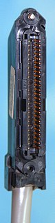
It is used to implement connections for up to 25 lines, or circuits that require many wire pairs, such as used in the 1A2 key telephone system.
Dual 50-pin ribbon connectors are often used on punch blocks to create a breakout box for private branch exchange (PBX) and other key telephone systems.
The RJ45S, an obsolete standard[9] jack once specified for modem or data interfaces, has a slot on one side to allow mating with a special variation of the 8P plug: a mechanically-keyed plug with an extra tab on one side that prevents it from mating with regular (non-keyed) 8P jacks.
RJ48X is a variation that contains shorting blocks in the jack for troubleshooting: With no plug inserted, pins 2 and 5 (the two tip wires) are connected to each other, and likewise 1 and 4 (ring), creating a loopback so that a signal received on one pair is returned on the other.
RJ48 connectors are fastened to shielded twisted pair (STP) cables, not the unshielded twisted-pair (UTP) commonly used in other installations.
This wiring pattern is for multi-line analog telephone use only; RJ61 is unsuitable for use with high-speed data because the pins for pairs 3 and 4 are too widely spaced for high signaling frequencies.
The flat eight-conductor silver-satin cable conventionally used with four-line analog telephones and RJ61 jacks is also unsuitable for use with high-speed data.
Twisted-pair patch cable typically used with common Ethernet and other data network standards is not compatible with RJ61, because RJ61 pairs 3 and 4 would each be split across two different twisted pairs in the patch cable, causing excessive cross-talk between voice lines 3 and 4, with conversations on each line literally being audible on the other.

- Eight-position, eight-contact (8P8C) plug , as used for RJ45S, RJ49, RJ61, and others (though shown wired in a pattern incompatible with RJ61)
- Six-position, six-contact (6P6C) plug, which can be used with RJ25, RJ14, and RJ11
- Six-position, four-contact (6P4C) plug, which can be used with RJ14 and RJ11 (and will carry lines 1 and 2, but not line 3, of an RJ25)
- Four-position, four-contact (4P4C) plug, used for connecting a telephone handset and base
- Six-position, six-contact (6P6C) jack , which could be wired as RJ11, RJ14, or RJ25335