Toroidal inductors and transformers
They are passive electronic components, consisting of a circular ring or donut shaped magnetic core of ferromagnetic material such as laminated iron, iron powder, or ferrite, around which wire is wound.
The advantage of the toroidal shape is that, due to its symmetry, the amount of magnetic flux that escapes outside the core (leakage flux) can be made low, potentially making it more efficient and making it emit less electromagnetic interference (EMI).
Toroidal inductors and transformers are used in a wide range of electronic circuits: power supplies, inverters, and amplifiers, which in turn are used in the vast majority of electrical equipment: TVs, radios, computers, and audio systems.
In general, a toroidal inductor/transformer is more compact than other shaped cores because they are made of fewer materials and include a centering washer, nuts, and bolts resulting in up to a 50% lighter weight design.
In addition, because the windings are relatively short and wound in a closed magnetic field, a toroidal transformer will have a lower secondary impedance which will increase efficiency, electrical performance and reduce effects such as distortion and fringing.
Thus, a toroidal inductor/transformer, radiates less electromagnetic interference (EMI) to adjacent circuits and is an ideal choice for highly concentrated environments.
[3] Manufacturers have adopted toroidal coils in recent years to comply with increasingly strict international standards limiting the amount of electromagnetic field consumer electronics can produce.
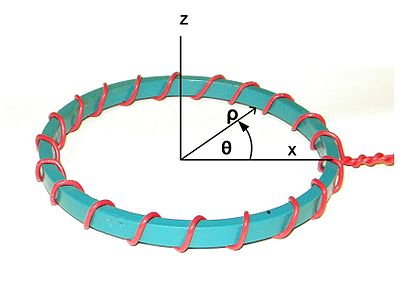
The absence of circumferential current [4] (the path of circumferential current is indicated by the red arrow in figure 3 of this section) and the axially symmetric layout of the conductors and magnetic materials [4][5][6] are sufficient conditions for total internal confinement of the B field.
Figure 4 is the simplest and has the advantage that the return wire can be added after the inductor is bought or built.
See Feynman page 15-11 [10] for a diagram of the magnetic vector potential around a long thin solenoid which also exhibits total internal confinement of the B field, at least in the infinite limit.
This would be true under the following assumptions: Number 4 will be presumed for the rest of this section and may be referred to the "quasi-static condition".
Radial current sections a and b are equal distances from the axis but pointed in opposite directions, so they will cancel.
The figure to the left is an artist's depiction of the A field around a toroidal inductor.
(scalar electric potential) fields Stokes theorem applies,[12] so that the path integral of A is equal to the enclosed B flux, just as the path integral B is equal to a constant times the enclosed current The path integral of E along the secondary winding gives the secondary's induced EMF (Electro-Motive Force).
which says the EMF is equal to the time rate of change of the B flux enclosed by the winding, which is the usual result.
The requirements are met for full internal confinement of the B field due to the primary current.
The secondary winding is shown as a brown line coming directly down the axis of symmetry.
In standard practice, the two ends of the secondary are connected with a long wire that stays well away from the torus, but to maintain the absolute axial symmetry, the entire apparatus is envisioned as being inside a perfectly conductive sphere with the secondary wire "grounded" to the inside of the sphere at each end.
The cross product of the E field (sourced from primary currents) and the B field (sourced from the secondary currents) forms the Poynting vector, which points from the primary toward the secondary.