Optical fiber
Such fibers find wide usage in fiber-optic communications, where they permit transmission over longer distances and at higher bandwidths (data transfer rates) than electrical cables.
[13] Daniel Colladon and Jacques Babinet first demonstrated the guiding of light by refraction, the principle that makes fiber optics possible, in Paris in the early 1840s.
Image transmission through tubes was demonstrated independently by the radio experimenter Clarence Hansell and the television pioneer John Logie Baird in the 1920s.
In the 1930s, Heinrich Lamm showed that one could transmit images through a bundle of unclad optical fibers and used it for internal medical examinations, but his work was largely forgotten.
[15][19] In 1953, Dutch scientist Bram van Heel first demonstrated image transmission through bundles of optical fibers with a transparent cladding.
[19][20][21] The first practical fiber optic semi-flexible gastroscope was patented by Basil Hirschowitz, C. Wilbur Peters, and Lawrence E. Curtiss, researchers at the University of Michigan, in 1956.
[19] Kapany coined the term fiber optics after writing a 1960 article in Scientific American that introduced the topic to a wide audience.
[19][22] The first working fiber-optic data transmission system was demonstrated by German physicist Manfred Börner at Telefunken Research Labs in Ulm in 1965, followed by the first patent application for this technology in 1966.
Chemical engineer Thomas Mensah joined Corning in 1983 and increased the speed of manufacture to over 50 meters per second, making optical fiber cables cheaper than traditional copper ones.
[36][37][38] The emerging field of photonic crystals led to the development in 1991 of photonic-crystal fiber,[39] which guides light by diffraction from a periodic structure, rather than by total internal reflection.
[53] These can be implemented by various micro- and nanofabrication technologies, such that they do not exceed the microscopic boundary of the fiber tip, allowing for such applications as insertion into blood vessels via hypodermic needle.
[55] While this method of power transmission is not as efficient as conventional ones, it is especially useful in situations where it is desirable not to have a metallic conductor as in the case of use near MRI machines, which produce strong magnetic fields.
A coherent bundle of fibers is used, sometimes along with lenses, for a long, thin imaging device called an endoscope, which is used to view objects through a small hole.
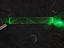
The resulting curved paths reduce multi-path dispersion because high-angle rays pass more through the lower-index periphery of the core, rather than the high-index center.
Dopants, such as germanium dioxide or fluorine, are used to create the refractive index difference between the core and the cladding, to form a waveguide structure.
where λ is wavelength, n is refractive index, p is photo-elastic coefficient, βc is isothermal compressibility, kB is the Boltzmann constant, Tf is fictive temperature.
Rc in pure silica core fiber is proportional to the overlap integral between LP01 mode and fluorine-induced concentration fluctuation component in the cladding.
In the core of potassium-doped pure silica-core (KPSC) fiber only density fluctuations play a significant role, as the concentrations of K2O, fluorine and chlorine are very low.
The density fluctuations in the core are moderated by lower fictive temperature resulting from potassium doping, and are further reduced by annealing during the fiber draw process.
The crystal structure absorption characteristics observed at the lower frequency regions (mid- to far-IR wavelength range) define the long-wavelength transparency limit of the material.
They are the result of the interactive coupling between the motions of thermally induced vibrations of the constituent atoms and molecules of the solid lattice and the incident light wave radiation.
Thus, although heavy metal fluoride glasses (HMFG) exhibit very low optical attenuation, they are not only difficult to manufacture, but are quite fragile, and have poor resistance to moisture and other environmental attacks.
Such low losses were never realized in practice, and the fragility and high cost of fluoride fibers made them less than ideal as primary candidates.
Fluoride fibers can be used for guided lightwave transmission in media such as YAG (yttrium aluminium garnet) lasers at 2.9 μm, as required for medical applications (e.g. ophthalmology and dentistry).
[82] With inside vapor deposition, the preform starts as a hollow glass tube approximately 40 centimeters (16 in) long, which is placed horizontally and rotated slowly on a lathe.
The gases are then heated by means of an external hydrogen burner, bringing the temperature of the gas up to 1,900 K (1,600 °C, 3,000 °F), where the tetrachlorides react with oxygen to produce silica or germanium dioxide particles.
The coatings protect the very delicate strands of glass fiber—about the size of a human hair—and allow it to survive the rigors of manufacturing, proof testing, cabling, and installation.
Three key characteristics of fiber optic waveguides can be affected by environmental conditions: strength, attenuation, and resistance to losses caused by microbending.
[91] For the most demanding installations, factory pre-polished pigtails of sufficient length to reach the first fusion splice enclosure assures good performance and minimizes on-site labor.
[96] This problem can be overcome in several ways, including the use of extra repeaters and the use of a relatively short length of fiber that has the opposite refractive index gradient.


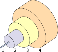
1. Core: 8 μm diameter
2. Cladding: 125 μm dia.
3. Buffer: 250 μm dia.
4. Jacket: 400 μm dia.


