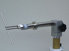
Dipole antenna
German physicist Heinrich Hertz first demonstrated the existence of radio waves in 1887 using what we now know as a dipole antenna (with capacitative end-loading).
[7](p 3) For the low frequencies Marconi employed to achieve long-distance communications, this form was more practical; when radio moved to higher frequencies (especially VHF transmissions for FM radio and TV) it was advantageous for these much smaller antennas to be entirely atop a tower thus requiring a dipole antenna or one of its variations.
In the early days of radio, the thus-named Marconi antenna (monopole) and the doublet (dipole) were seen as distinct inventions.
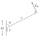
From the fields calculated above, one can find the radiated flux (power per unit area) at any point as the magnitude of the real part of the Poynting vector, S, which is given by
the phase factors (the exponentials) cancel out, leaving: We have now expressed the flux in terms of the feedpoint current Io and the ratio of the short dipole's length ℓ to the wavelength of radiation λ.
Dipoles which are an odd number of half-wavelengths in length have reasonably low driving point impedances (which are purely resistive at that resonant frequency).
They can be used for transforming the value of input impedance of the dipole over a broad range of step-up ratios by changing the thicknesses of the wire conductors for the fed- and folded-sides.
[13] Instead of altering thickness or spacing, one can add a third parallel wire to increase the antenna impedance to 9 times that of a single-wire dipole, raising the impedance to 658 Ω, making a good match for open wire feed cable, and further broadening the resonant frequency band of the antenna.
There are numerous modifications to the shape of a dipole antenna which are useful in one way or another but result in similar radiation characteristics (low gain).
This is not an actual performance advantage per se, since in practice a dipole also reflects half of its power off the ground which (depending on the antenna height and sky angle) can augment (or cancel!)
[8][9] Therefore, a dipole will generally only perform optimally over a rather narrow bandwidth, beyond which its impedance will become a poor match for the transmitter or receiver (and transmission line).
The real (resistive) and imaginary (reactive) components of that impedance, as a function of electrical length, are shown in the accompanying graph.
For the same reason, antennas with thicker conductors have a wider operating bandwidth over which they attain a practical standing wave ratio which is degraded by any remaining reactance.
Ideally, a half-wave dipole should be fed using a balanced transmission line matching its typical 65–70 Ω input impedance.
Twin lead with a similar impedance is available but seldom used and does not match the balanced antenna terminals of most radio and television receivers.
[19][full citation needed] Most FM broadcast band tuners and older analog televisions include balanced 300 Ω antenna input terminals.
Many types of coaxial cable (or coax) have a characteristic impedance of 75 Ω, which would otherwise be a good match for a half-wave dipole.
[20][24] A coax balun is a cost-effective method of eliminating feeder radiation but is limited to a narrow set of operating frequencies.
For fixed use in homes, hi-fi tuners are typically supplied with simple folded dipoles resonant near the center of that band.
Vertical collinear arrays are used in the VHF and UHF frequency bands at which wavelengths the size of the elements are small enough to practically stack several on a mast.
They are a higher-gain alternative to quarter-wave ground plane antennas used in fixed base stations for mobile two-way radios, such as police, fire, and taxi dispatchers.
In the popular high-gain Yagi antenna, only one of the dipoles is actually connected electrically, but the others receive and reradiate power supplied by the driven element.
Although the realized gain is less than a driven array with the same number of elements, the simplicity of the electrical connections makes the Yagi more practical for consumer applications.
The Hertzian dipole or elementary doublet refers to a theoretical construction, rather than a physical antenna design: It is an idealized tiny segment of conductor carrying a RF current with constant amplitude and direction along its entire (short) length; a real antenna can be modeled as the combination of many Hertzian dipoles laid end-to-end.
the resulting field pattern then reduces to an integral over the path of an antenna conductor (modeled as a thin wire).
In both cases the conductor is very short compared to a wavelength, so the standing wave pattern present on a half-wave dipole (for instance) is absent.
Using the induced EMF method closed form expressions are obtained for both components of the feedpoint impedance; such results are plotted above.
In cases where an approximately sinusoidal current distribution can be assumed, this method solves for the driving point impedance in closed form using the cosine and sine integral functions Si(x) and Ci(x) .
[e] The induced EMF method is dependent on the assumption of a sinusoidal current distribution, delivering an accuracy better than about 10% as long as the wavelength-to-element diameter ratio is greater than about 60.
Determination of each matrix element requires at least one double integration involving the weighting functions, which may become computationally intensive.