Clutter (radar)
Clutter[1][2] is the unwanted return (echoes) in electronic systems, particularly in reference to radars.
Such echoes are typically returned from ground, sea, rain, animals/insects, chaff and atmospheric turbulences, and can cause serious performance issues with radar systems.
The clutter may fill a volume (such as rain) or be confined to a surface (like land).
A knowledge of the volume or surface area illuminated is required to estimated the echo per unit volume, η, or echo per unit surface area, σ° (the radar backscatter coefficient).
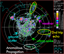
Clutter may be caused by man-made objects such as buildings and — intentionally — by radar countermeasures such as chaff.
Other causes include natural objects such as terrain features, sea, precipitation, hail spike, dust storms, birds, turbulence in the atmospheric circulation, and meteor trails.
This phenomenon is especially apparent near the geomagnetic poles, where the action of the solar wind on the earth’s magnetosphere produces convection patterns in the ionospheric plasma.
[3][4] Clutter may also originate from multipath echoes from valid targets caused by ground reflection, atmospheric ducting or ionospheric reflection/refraction (e.g., anomalous propagation).
This clutter type is especially bothersome since it appears to move and behave like common targets of interest, such as aircraft or weather balloons.
The total signal competing with the target return is thus clutter plus noise.
Rain, hail, snow and chaff are examples of volume clutter.
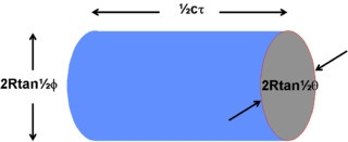
respectively if the illuminated cell is assumed to have an elliptical cross section.
The volume of the illuminated cell is thus: For small angles this simplifies to: The clutter is assumed to be a large number of independent scatterers that fill the cell containing the target uniformly.
The clutter return from the volume is calculated as for the normal radar equation but the radar cross section is replaced by the product of the volume backscatter coefficient,
The correction factor is found by integrating across the beam width the Gaussian approximation of the antenna.
The corrected back scattered power is A number of simplifying substitutions can be made.
The receiving antenna aperture is related to its gain by: and the antenna gain is related to the two beamwidths by: The same antenna is generally used both for transmission and reception thus the received clutter power is: If the Clutter Return Power is greater than the System Noise Power then the Radar is clutter limited and the Signal to Clutter Ratio must be equal to or greater than the Minimum Signal to Noise Ratio for the target to be detectable.
From the radar equation the return from the target itself will be with a resulting expression for the signal to clutter ratio of The implication is that when the radar is noise limited the variation of signal to noise ratio is an inverse fourth power.
Halving the distance will cause the signal to noise ratio to increase (improve) by a factor of 16.
When the radar is volume clutter limited, however, the variation is an inverse square law and halving the distance will cause the signal to clutter to improve by only 4 times.
At a range of 10 km the beam could cover from ground level to a height of 1750 metres.
The reflected signal is the phasor sum of a large number of individual returns from a variety of sources, some of them capable of movement (leaves, rain drops, ripples) and some of them stationary (pylons, buildings, tree trunks).
The most common case is when the beam intersects the surface at such an angle that the area illuminated at any one time is only a fraction of the surface intersected by the beam as illustrated in Figure 2.
to degrees and putting in the numerical values gives The expression for the target return remains unchanged thus the signal to clutter ratio is This simplifies to In the case of surface clutter the signal to clutter now varies inversely with R. Halving the distance only causes a doubling of the ratio (a factor of two improvement).
The calculation is similar to the previous examples, in this case the illuminated area is which for small beamwidths simplifies to The clutter return is as before Substituting for the illuminated area
Various empirical formulae and graphs exist which enable an estimate to be made but the results need to be used with caution.
[6] The solution to this problem is usually to add fill pulses to each coherent dwell of the radar, increasing the range over which clutter suppression is applied by the system.
The tradeoff for doing this is that adding fill pulses will degrade the performance, due to wasted transmitter power and a longer dwell time.