Gun laying
Indirect fire is determined from the information or data that is collected, calculated, and applied to physical coordinates to identify the location of the target by the user.
With indirect fire the horizontal angle is relative to something, typically the gun's aiming point, although with modern electronic sights it may be a north-seeking gyro.
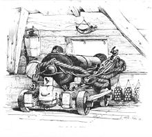
Early guns could only be traversed by moving their entire carriage or mounting, and this lasted with heavy artillery into World War II.
However, mortars, where the recoil forces were transferred directly into the ground (or water, if mounted on a ship), did not always require such movement.
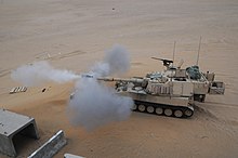
With the adoption of recoil systems for field artillery, it became normal to pivot the saddle on the lower carriage, initially this "top traverse" was only a few degrees but soon offered a full circle, particularly for anti-aircraft guns.
Horizontal alignment with the target was by eye, while vertical laying was done by raising the muzzle with timber or digging a hole for the closed end.
However, while point blank may have been enough for some purposes, field artillery (whether mobile or static) and guns in fortresses needed longer range.
The problem was that these calculations assumed what today is called an "in vacuo" trajectory – they made no allowance for air resistance against the projectile.
[5] The practical approach was conducted by William Eldred, Master Gunner at Dover Castle, in gunnery trials in 1613, 1617 and 1622.
From the results of these trials, he produced range tables for elevations up to 10 degrees for each type with a standard propelling charge weight.
Robins experimented with musket balls of around one ounce in mass (30 g), while other contemporaries used his methods with cannon shot of one to three pounds (0.45 to 1.36 kg).
A direct electromechanical clockwork measure appeared in 1840, with a spring-driven clock started and stopped by electromagnets, whose current was interrupted by the bullet passing through two meshes of fine wires, again providing the time to traverse the given distance.
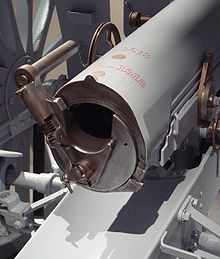
By the late 19th century the simple open tangent sights were being replaced by optical telescopes on mounts with an elevation scale and screw aligned to the axis of the bore.
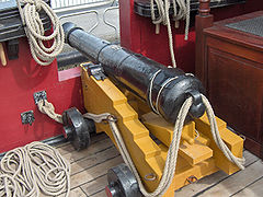
[9] Rifled and breech loading artillery were introduced from the mid-19th century, notably by William Armstrong, whose gun equipped Royal Navy warships from the 1850s.
A related problem, particularly for large and longer range guns, was that the wheels could be at different heights due to the slope of the ground, which caused inaccuracy.
These mounts could be cross-leveled, which removed the need for the gun commander to calculate a deflection correction for uneven wheels.
In 1882, Russian Lt Col KG Guk published Field Artillery Fire from Covered Positions that described a better method of indirect laying (instead of aiming points in line with the target).
[15] Although both sides demonstrated early on in the conflict that could use the technique effectively, in many subsequent battles, British commanders nonetheless ordered artillery to be "less timid" and to move forward to address troops' concerns about their guns abandoning them.
This issue became more complicated in World War I when the effects of barrel wear in changing muzzle velocity were fully recognised.
The issue was finally resolved by the introduction of digital computers in the battery command post that calculated the correct elevation angle for the range and muzzle velocity accurately and quickly.
However, in the 1990s new or modified guns started adopting digital sights, following their successful use in the multi-launch rocket system developed in the 1970s.
This computed a correction for the cross level of the gun and used feedback from electro-mechanical devices, such as gyroscopes and electronic clinometers, aligned to the axis of the bore.
His description explains its essence: It took almost 20 years to get it to full effectiveness, but its general principle became the norm for heavy artillery fire control and laying.
In the 20th century, coast artillery, like field and the larger anti-aircraft guns, included corrections for non-standard conditions such as wind and temperature in their calculations.
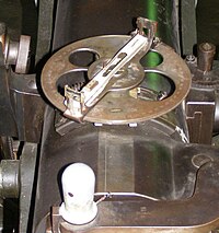
Increasingly sophisticated mechanical calculators were employed for proper gun laying, typically with various spotters and distance measures being sent to a central plotting station deep within the ship.
Pollen began working on the problem after noting the poor accuracy of naval artillery at a gunnery practice near Malta in 1900.
[19] Lord Kelvin, widely regarded as Britain's leading scientist first proposed using an analogue computer to solve the equations which arise from the relative motion of the ships engaged in the battle and the time delay in the flight of the shell to calculate the required trajectory and therefore the direction and elevation of the guns.
Pollen aimed to produce a combined mechanical computer and automatic plot of ranges and rates for use in centralised fire control.
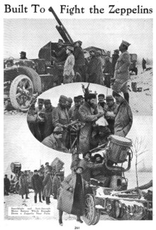
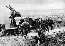
In either case the problem is determining the target's height, speed and direction and being able to 'aim-off' (sometimes called deflection laying) for the anti-aircraft projectile time of flight.
Both France and UK introduced tachymetric devices to track targets and produce vertical and horizontal deflection angles.