Hydraulic power network
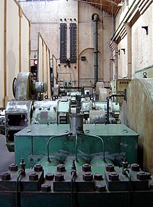
In the late 19th century, a hydraulic network might have been used in a factory, with a central steam engine or water turbine driving a pump and a system of high-pressure pipes transmitting power to various machines.
William Armstrong began installing systems in England from the 1840s, using low-pressure water, but a breakthrough occurred in 1850 with the introduction of the hydraulic accumulator, which allowed much higher pressures to be used.
Joseph Bramah, an inventor and locksmith living in London, registered a patent at the London Patent Office on 29 April 1812, which was principally about a provision of a public water supply network, but included a secondary concept for the provision of a high-pressure water main, which would enable workshops to operate machinery.
[2] Bramah's concept of "loaded pistons" was introduced in 1850, when the first hydraulic accumulator was installed as part of a scheme for cranes for the Manchester, Sheffield and Lincolnshire Railway.
A scheme for cranes at Paddington the following year specified an accumulator with a 10-inch (250 mm) piston and a stroke of 15 feet (4.6 m), which enabled pressures of 600 pounds per square inch (41 bar) to be achieved.
They had 2.5 miles (4.0 km) of pipes, which were up to 6 inches (150 mm) in diameter, and ran along the west bank of the River Hull from Sculcoates bridge to its junction with the Humber.
The working pressure was 700 psi (48 bar), and the water was used to operate cranes, dock gates, and a variety of other machinery connected with ships and shipbuilding.
The Hull system lasted until the 1940s, when the systematic bombing of the city during the Second World War led to the destruction of much of the infrastructure,[5] and the company was wound up in 1947,[6] when Mr F J Haswell, who had been the manager and engineer since 1904, retired.
[7] The man responsible for the Hull system was Edward B. Ellington, who had risen to become the managing director of the Hydraulic Engineering Company, based in Chester, since first joining it in 1869.
The success of such systems led to them being installed in places as far away as Antwerp in Belgium, Melbourne and Sydney in Australia, and Buenos Aires in Argentina.
They maintained 184 miles (296 km) of mains at 700 psi (48 bar), which covered an area reaching Pentonville in the north, Limehouse in the east, Nine Elms and Bermondsey in the south and Earls Court and Notting Hill in the west.
A fifth station at East India Docks was originally operated by the Port of London Authority, but was taken over and connected to the system.
While the network supplied lifts, cranes and dockgates, it also powered the cabaret platform at the Savoy Hotel, and from 1937, the 720-tonne three-section central floor at the Earls Court Exhibition Centre, which could be raised or lowered relative to the main floor to convert between a swimming pool and an exhibition hall.
Following the hostilities, large areas of London were reconstructed, and the re-routing of pressure mains was much more difficult than the provision of an electric supply, so that by 1954 the number of machines had fallen to 4,286.
[14] By 1890, some 16 miles (26 km) of mains had been installed, supplied by a pumping station at Athol Street, on the bank of the Leeds and Liverpool Canal.
In an unusual move, J. W. Gray, the Water Department engineer for the city, had been laying pressure mains beneath the streets for some years, anticipating the need for such a system.
The hydraulic station used Otto 'Silent' type gas engines, and had two accumulators, with an 18-inch (460 mm) diameter piston, a stroke of 20 feet (6.1 m) and each loaded with a 93-tonne weight.
[19] The pipes were 7 inches (180 mm) in diameter, and there were around 30 miles (48 km) of them by 1909, when 202,141 imperial gallons (918.95 m3) of high pressure water were supplied to customers.
[22] All of the British systems were designed to provide power for intermittent processes, such as the operation of dock gates or cranes.
Ellington, writing in 1895, stated that he found it difficult to see that this was an economical use of hydraulic power, although tests conducted at his works at Chester in October 1894 showed that efficiencies of 59 per cent could be achieved using a Pelton wheel directly coupled to a dynamo.
George Swinburne was again the engineer, and the system was supplying power to around 200 machines by 1894, which included 149 lifts and 20 dock cranes.
[31] In order to avoid excessive pressure build-up in the hydraulic power network, a release valve was fitted beside the main hall of the powerhouse.
When an engineering solution was found which made the fountain redundant, there was an outcry, and in 1891 it was moved to its current location in the lake, where it operated solely as a tourist attraction, although the water to create it still came from the hydraulic network.
With water sourced from the Waitaki River, the race stretched nearly 50 km and comprised an intake structure, a stilling pond, 19 aqueducts and six tunnels.
[36] Bristol Harbour still has a working system, the pumping machinery of which was supplied by Fullerton, Hodgart and Barclay of Paisley, Scotland in 1907.
A number of artefacts, including the buildings used as pumping stations, have survived the demise of public hydraulic power networks.
The building still supports the sectional cast-iron roof tank used to allow the silt-laden water of the River Hull to settle, and is marked by a Blue plaque, to commemorate its importance.
[39] In Manchester, the Water Street pumping station, built in Baroque style between 1907 and 1909, was used as workshops for the City College,[40] but has formed part of the People's History Museum since 1994.
One of the pumping sets has been moved to the Museum of Science and Industry, where it has been restored to working order and forms part of a larger display about hydraulic power.
Two Sulzer pumps, named Jura and Salève, create a fountain which rises to a height of 460 feet (140 m) above the surface of the lake.