Instrument landing system
Bringing the aircraft this close to the runway dramatically increases the range of weather conditions in which a safe landing can be made.
Other versions of the system, or "categories", have further reduced the minimum altitudes, runway visual ranges (RVRs), and transmitter and monitoring configurations designed depending on the normal expected weather patterns and airport safety requirements.
[1] A number of radio-based landing systems were developed between the 1920s and 1940s, notably the Lorenz beam which saw relatively wide use in Europe prior to World War II.
The introduction of precision approaches using global navigation satellite systems (GNSSs) instead of requiring expensive airport infrastructure is leading to the replacement of ILS.
These normally consisted of a radio transmitter that was connected to a motorized switch to produce a pattern of Morse code dots and dashes.
They would hear dots and dashes (Morse code "A" or "N"), if they were to the side of the runway, or if they were properly aligned, the two mixed together to produce a steady tone, the equisignal.
The accuracy of this measurement was highly dependent on the skill of the operator, who listened to the signal on earphones in a noisy aircraft, often while communicating with the tower.
[3] The ILS, developed just prior to the start of World War II, used a more complex system of signals and an antenna array to achieve higher accuracy.
This requires significantly more complexity in the ground station and transmitters, with the advantage that the signals can be accurately decoded in the aircraft using simple electronics and displayed directly on analog instruments.
[4] As the measurement compares different parts of a single signal entirely in electronics, it provides angular resolution of less than a degree, and allows the construction of a precision approach.
[4] Although the encoding scheme is complex, and requires a considerable amount of ground equipment, the resulting signal is both far more accurate than the older beam-based systems and is far more resistant to common forms of interference.
Similarly, changes in overall signal strength as the aircraft approaches the runway, or changes due to fading, will have little effect on the resulting measurement because they would normally affect both channels equally.
In the older beam systems, the accuracy of the equisignal area was a function of the pattern of the two directional signals, which demanded that they be relatively narrow.
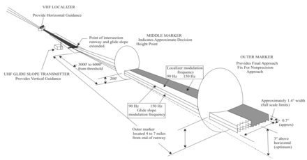
[5] The glideslope works in the same general fashion as the localizer and uses the same encoding, but is normally transmitted to produce a centerline at an angle of 3 degrees above horizontal[a] from an antenna beside the runway instead of the end.
These illustrations are inaccurate; both signals are radiated across the entire beam pattern, it is their relative difference in the depth of modulation (DDM) that changes dependent upon the position of the approaching aircraft.
The pilot controls the aircraft so that the glide slope indicator remains centered on the display to ensure the aircraft is following the glide path of approximately 3° above horizontal (ground level) to remain above obstructions and reach the runway at the proper touchdown point (i.e. it provides vertical guidance).
Additionally, since the ILS signals are pointed in one direction by the positioning of the arrays, glide slope supports only straight-line approaches with a constant angle of descent.
If any significant deviation beyond strict limits is detected, either the ILS is automatically switched off or the navigation and identification components are removed from the carrier.
In the United States, back course approaches are typically associated with Category I systems at smaller airports that do not have an ILS on both ends of the primary runway.
The distance from the runway at which this indication should be received is published in the documentation for that approach, together with the height at which the aircraft should be if correctly established on the ILS.
Co-located with the ILS glidepath transmitter near the touchdown point, the DME provides a display of aircraft distance to the runway.
The DME provides more accurate and continuous monitoring of correct progress on the ILS glide slope to the pilot, and does not require an installation outside the airport boundary.
[11] In contrast to other operations, CAT III weather minima do not provide sufficient visual references to allow a manual landing to be made.
CAT IIIb RVR minimums are limited by the runway/taxiway lighting and support facilities, and are consistent with the airport surface movement guidance control system (SMGCS) plan.
If the CAT IIIb RVR minimums on a runway end are 600 feet (180 m), which is a common figure in the U.S., ILS approaches to that runway end with RVR below 600 feet (180 m) qualify as CAT IIIc and require special taxi procedures, lighting, and approval conditions to permit the landings.
Some modern aircraft are equipped with enhanced flight vision systems based on infrared sensors, that provide a day-like visual environment and allow operations in conditions and at airports that would otherwise not be suitable for a landing.
The design takes into consideration additional safety requirements for operating an aircraft close to the ground and the ability of the flight crew to react to a system anomaly.
Typically, an aircraft is established by at least 2 nautical miles (3.7 km) prior to the final approach fix (glideslope intercept at the specified altitude).
Tests of the ILS began in 1929 in the United States, with Jimmy Doolittle becoming the first pilot to take off, fly and land an airplane using instruments alone, without a view outside the cockpit.
The equivalent European Geostationary Navigation Overlay Service (EGNOS) was certified for use in safety of life applications in March 2011.