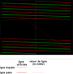
Interlaced video
This enhances motion perception to the viewer, and reduces flicker by taking advantage of the characteristics of the human visual system.
[4][5] The main argument is that no matter how complex the deinterlacing algorithm may be, the artifacts in the interlaced signal cannot be completely eliminated because some information is lost between frames.
Given a fixed bandwidth and high refresh rate, interlaced video can also provide a higher spatial resolution than progressive scan.
Minor Y axis motion can be corrected similarly by aligning the scanlines in a different sequence and cropping the excess at the top and bottom.
Professional video cameras or computer-generated imagery systems apply a low-pass filter to the vertical resolution of the signal to prevent interline twitter.
When the overall interlaced framerate is 60 frames per second, a pixel (or more critically for e.g. windowing systems or underlined text, a horizontal line) that spans only one scanline in height is visible for the 1/60 of a second that would be expected of a 60 Hz progressive display - but is then followed by 1/60 of a second of darkness (whilst the opposite field is scanned), reducing the per-line/per-pixel refresh rate to 30 frames per second with quite obvious flicker.
Most fonts for television programming have wide, fat strokes, and do not include fine-detail serifs that would make the twittering more visible; in addition, modern character generators apply a degree of anti-aliasing that has a similar line-spanning effect to the aforementioned full-frame low-pass filter.
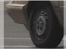
Real interlaced video blurs such details to prevent twitter, as seen in the bottom row, but such softening (or anti-aliasing) comes at the cost of image clarity.
Providing the best picture quality for interlaced video signals without doubling the frame rate requires expensive and complex devices and algorithms, and can cause various artifacts.
Current manufacture TV sets employ a system of intelligently extrapolating the extra information that would be present in a progressive signal entirely from an interlaced original.
In practice, results are currently variable, and depend on the quality of the input signal and amount of processing power applied to the conversion.
When motion picture film was developed, the movie screen had to be illuminated at a high rate to prevent visible flicker.
In addition, avoiding on-screen interference patterns caused by studio lighting and the limits of vacuum tube technology required that CRTs for TV be scanned at AC line frequency.
[13] In 1930, German Telefunken engineer Fritz Schröter first formulated and patented the concept of breaking a single image frame into successive interlaced lines, based on his earlier experiments with phototelegraphy.
[11][14] In the USA, RCA engineer Randall C. Ballard patented the same idea in 1932, initially for the purpose of reformatting sound film to television rather than for the transmission of live images.
[11][15][16] Commercial implementation began in 1934 as cathode-ray tube screens became brighter, increasing the level of flicker caused by progressive (sequential) scanning.
[12] In 1936, when the UK was setting analog standards, early thermionic valve based CRT drive electronics could only scan at around 200 lines in 1/50 of a second (i.e. approximately a 10 kHz repetition rate for the sawtooth horizontal deflection waveform).
Using interlace, a pair of 202.5-line fields could be superimposed to become a sharper 405 line frame (with around 377 used for the actual image, and yet fewer visible within the screen bezel; in modern parlance, the standard would be "377i").
France instead adopted its own unique, twin-FM-carrier based SECAM system, which offered improved quality at the cost of greater electronic complexity, and was also used by some other countries, notably Russia and its satellite states.
While consumer devices were permitted to create such signals, broadcast regulations prohibited TV stations from transmitting video like this.
IBM's Monochrome Display Adapter and Enhanced Graphics Adapter as well as the Hercules Graphics Card and the original Macintosh computer generated video signals of 342 to 350p, at 50 to 60 Hz, with approximately 16 MHz of bandwidth, some enhanced PC clones such as the AT&T 6300 (aka Olivetti M24) as well as computers made for the Japanese home market managed 400p instead at around 24 MHz, and the Atari ST pushed that to 71 Hz with 32 MHz bandwidth - all of which required dedicated high-frequency (and usually single-mode, i.e. not "video"-compatible) monitors due to their increased line rates.
This ability (plus built-in genlocking) resulted in the Amiga dominating the video production field until the mid-1990s, but the interlaced display mode caused flicker problems for more traditional PC applications where single-pixel detail is required, with "flicker-fixer" scan-doubler peripherals plus high-frequency RGB monitors (or Commodore's own specialist scan-conversion A2024 monitor) being popular, if expensive, purchases amongst power users.
In the late 1980s and early 1990s, monitor and graphics card manufacturers introduced newer high resolution standards that once again included interlace.
Such monitors proved generally unpopular, outside of specialist ultra-high-resolution applications such as CAD and DTP which demanded as many pixels as possible, with interlace being a necessary evil and better than trying to use the progressive-scan equivalents.
Whilst flicker was often not immediately obvious on these displays, eyestrain and lack of focus nevertheless became a serious problem, and the trade-off for a longer afterglow was reduced brightness and poor response to moving images, leaving visible and often off-colored trails behind.
These colored trails were a minor annoyance for monochrome displays, and the generally slower-updating screens used for design or database-query purposes, but much more troublesome for color displays and the faster motions inherent in the increasingly popular window-based operating systems, as well as the full-screen scrolling in WYSIWYG word-processors, spreadsheets, and of course for high-action games.
Additionally, the regular, thin horizontal lines common to early GUIs, combined with low color depth that meant window elements were generally high-contrast (indeed, frequently stark black-and-white), made shimmer even more obvious than with otherwise lower fieldrate video applications.
As rapid technological advancement made it practical and affordable, barely a decade after the first ultra-high-resolution interlaced upgrades appeared for the IBM PC, to provide sufficiently high pixel clocks and horizontal scan rates for hi-rez progressive-scan modes in first professional and then consumer-grade displays, the practice was soon abandoned.
For the rest of the 1990s, monitors and graphics cards instead made great play of their highest stated resolutions being "non-interlaced", even where the overall framerate was barely any higher than what it had been for the interlaced modes (e.g. SVGA at 56p versus 43i to 47i), and usually including a top mode technically exceeding the CRT's actual resolution (number of color-phosphor triads) which meant there was no additional image clarity to be gained through interlacing and/or increasing the signal bandwidth still further.
This experience is why the PC industry today remains against interlace in HDTV, and lobbied for the 720p standard, and continues to push for the adoption of 1080p (at 60 Hz for NTSC legacy countries, and 50 Hz for PAL); however, 1080i remains the most common HD broadcast resolution, if only for reasons of backward compatibility with older HDTV hardware that cannot support 1080p - and sometimes not even 720p - without the addition of an external scaler, similar to how and why most SD-focussed digital broadcasting still relies on the otherwise obsolete MPEG2 standard embedded into e.g. DVB-T.