Mason's gain formula
Mason's gain formula (MGF) is a method for finding the transfer function of a linear signal-flow graph (SFG).
The formula was derived by Samuel Jefferson Mason,[1] for whom it is named.
Often, MGF can be determined by inspection of the SFG.
MGF comes up often in the context of control systems, microwave circuits and digital filters because these are often represented by SFGs.
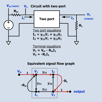
where: Source:[2] The transfer function from Vin to V2 is desired.
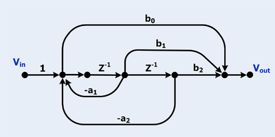
There is only one forward path: There are three loops: Digital filters are often diagramed as signal flow graphs.
The signal flow graph has six loops.
Mason's rule can be stated in a simple matrix form.
Mason's Rule is also particularly useful for deriving the z-domain transfer function of discrete networks that have inner feedback loops embedded within outer feedback loops (nested loops).
If the discrete network can be drawn as a signal flow graph, then the application of Mason's Rule will give that network's z-domain H(z) transfer function.
Mason's Rule can grow factorially, because the enumeration of paths in a directed graph grows dramatically.
Thus Gaussian elimination is more efficient in the general case.
Yet Mason's rule characterizes the transfer functions of interconnected systems in a way which is simultaneously algebraic and combinatorial, allowing for general statements and other computations in algebraic systems theory.
While numerous inverses occur during Gaussian elimination, Mason's rule naturally collects these into a single quasi-inverse.
is a sum of cycle products, each of which typically falls into an ideal (for example, the strictly causal operators).
Fractions of this form make a subring