Mechanical television
Mechanical-scan systems were largely superseded by electronic-scan technology in the mid-1930s, which was used in the first commercially successful television broadcasts which began in the late 1930s.
In the U.S., experimental stations such as W2XAB in New York City began broadcasting mechanical television programs in 1931 but discontinued operations on February 20, 1933, until returning with an all-electronic system in 1939.
The first practical facsimile system, working on telegraph lines, was developed and put into service by Giovanni Caselli from 1856 onward.
[5] In 1885, Henry Sutton in Ballarat, Australia designed what he called a telephane for transmission of images via telegraph wires, based on the Nipkow spinning disk system, selenium photocell, Nicol prisms and Kerr effect cell.
[9] The first demonstration of the instantaneous transmission of images was made by a German physicist, Ernst Ruhmer, who arranged 25 selenium cells as the picture elements for a television receiver.
In late 1909 he announced the transmission of simple images over a telephone wire from the Palace of Justice at Brussels to the city of Liège in Belgium, a distance of 70 miles (115 km).
[12] The publicity generated by Ruhmer's demonstration spurred two French scientists, Georges Rignoux and A. Fournier in Paris, to announce similar research that they had been conducting.
It was the 1907 invention of the first amplifying vacuum tube, the triode, by Lee de Forest, that made the design practical.
[17] Scottish inventor John Logie Baird in 1925 built some of the first prototype video systems, which employed the Nipkow disk.
On March 25, 1925, Baird gave the first public demonstration of televised silhouette images in motion, at Selfridge's Department Store in London.
A brightly illuminated subject was placed in front of a spinning Nipkow disk set with lenses that swept images across a static photocell.
The thallium sulfide (thalofide) cell, developed by Theodore Case in the USA, detected the light reflected from the subject and converted it into a proportional electrical signal.
This was transmitted by AM radio waves to a receiver unit, where the video signal was applied to a neon light behind a second Nipkow disk rotating synchronized with the first.
On December 25, 1925, Kenjiro Takayanagi demonstrated a television system with a 40-line resolution that employed a Nipkow disk scanner and CRT display at Hamamatsu Industrial High School in Japan.
[22] Herbert E. Ives and Frank Gray of Bell Telephone Laboratories gave a dramatic demonstration of mechanical television on April 7, 1927.
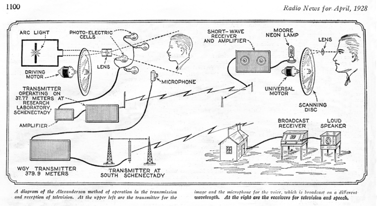
"[26] In 1928, General Electric launched their own experimental television station W2XB, broadcasting from the GE plant in Schenectady, New York.
Nevertheless, the image quality of 30-line transmissions steadily improved with technical advances, and by 1933 the UK broadcasts using the Baird system were remarkably clear.
The Earth receiving stations included electronic equipment that converted the raw color video signals into the NTSC standard.
The last mechanical television broadcasts ended in 1939 at stations run by a handful of public universities in the United States.
It used 39 vacuum tubes in its electronic circuits, and consumed around 1,000 W. Although producing impressive results and reaching the marketplace, the receiver was very expensive, costing around twice as much as a cathode-ray television.
These cameras use a high-sensitivity infrared photo receptor (usually cooled to increase sensitivity), but instead of conventional lenses, these systems use rotating prisms to provide a 525 or 625-line standard video output.
The most common method for creating the video signal was the "flying spot scanner", developed as a remedy for the low sensitivity that photoelectric cells had at the time.
In the scanner the narrow light beam was produced by an arc lamp shining through the holes in a spinning Nipkow disk.
Kell's photocells couldn't discriminate reflections off Smith (from the AC scanning beam) from the flat, DC light from the floodlamps.
A few mechanical TV systems could produce images several feet or meters wide and of comparable quality to the CRT televisions that were to follow.
(For example, the television systems of Ernst Alexanderson, Frank Conrad, Charles Francis Jenkins, William Peck[39] and Ulises Armand Sanabria.
Marketed as "Phonovision", this system, which was never fully perfected, proved to be complicated to use as well as quite expensive, yet managed to preserve a number of early broadcast images that would otherwise have been lost.
[41] Among the discs in Dr. McLean's collection are a number of test recordings made by television pioneer John Logie Baird himself.
One disc, dated "28th March 1928" and marked with the title "Miss Pounsford", shows several minutes of a woman's face in what appears to be very animated conversation.
In 1993, the woman was identified by relatives as Mabel Pounsford, and her brief appearance on the disc is one of the earliest known television video recordings of a human.