USB hardware
Higher-speed development of the USB standard gave rise to another family of connectors to permit additional data paths.
USB has been selected as the standard charging format for many mobile phones, reducing the proliferation of proprietary chargers.
Only downstream facing ports provide power; this topology was chosen to easily prevent electrical overloads and damaged equipment.
The three sizes of USB connectors are the default, or standard, format intended for desktop or portable equipment, the mini intended for mobile equipment, which was deprecated when it was replaced by the thinner micro size, all of which were deprecated in USB 3.2 in favor of Type-C.
The USB specification requires that the cable plug and receptacle be marked so the user can recognize the proper orientation.
[6] To accomplish this, a locking device was added and the leaf-spring was moved from the jack to the plug, so that the most-stressed part is on the cable side of the connection.
The USB specification also defines limits to the size of a connecting device in the area around its plug, so that adjacent ports are not blocked.
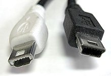
[3] Mini-USB connectors were introduced together with USB 2.0 in April 2000, mostly used with smaller devices such as digital cameras, smartphones, and tablet computers.
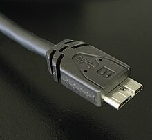
Micro-USB connectors, which were announced by the USB-IF on January 4, 2007,[15][16] have a similar width to Mini-USB, but approximately half the thickness, enabling their integration into thinner portable devices.
[19] Micro-USB was embraced as the "Universal Charging Solution" by the International Telecommunication Union (ITU) in October 2009.
The Micro-AB receptacle is capable of accepting Micro-A and Micro-B plugs, attached to any of the legal cables and adapters as defined in revision 1.01 of the Micro-USB specification.
The OTG device with the A-plug inserted is called the A-device and is responsible for powering the USB interface when required, and by default assumes the role of host.
[27] The USB-C plug connects to both hosts and devices, replacing various Type-A and Type-B connectors and cables with a standard meant to be future-proof.
[31] Full-featured USB-C 3.1 cables contain a full set of wires and are "electronically marked" (E-marked): they contain a "eMarker" chip that responds to the USB Power Delivery Discover Identity command, a kind of vendor-defined message (VDM) sent over the configuration data channel (CC).
Manufacturers of personal electronic devices might not include a USB standard connector on their product for technical or marketing reasons.
Some manufacturers provide proprietary cables, such as Lightning, that permit their devices to physically connect to a USB standard port.
[35] The D± signals used by low, full, and high speed are carried over a twisted pair (typically unshielded) to reduce noise and crosstalk.
[37][38][39] USB 2.0 provides for a maximum cable length of 5 metres (16 ft 5 in) for devices running at high speed (480 Mbit/s).
[39] The USB 2.0 specification requires that cable delay be less than 5.2 ns/m (1.6 ns/ft, 192000 km/s), which is close to the maximum achievable transmission speed for standard copper wire.
Dedicated charging ports can be found on USB power adapters to run attached devices and battery packs.
The charging port must not apply current limiting below 0.5 A, and must not shut down below 1.5 A or before the voltage drops to 2 V.[52] Since these currents are larger than in the original standard, the extra voltage drop in the cable reduces noise margins, causing problems with High Speed signaling.
It made several changes, and increased limits including allowing 1.5 A on charging downstream ports for unconfigured devices—allowing High Speed communication while having a current up to 1.5 A.
USB-PD Devices can request higher currents and supply voltages from compliant hosts—up to 2 A at 5 V (for a power consumption of up to 10 W), and optionally up to 3 A or 5 A at either 12 V (36 W or 60 W) or 20 V (60 W or 100 W).
[67] Power Delivery protocols have been updated to facilitate USB-C features such as cable ID function, Alternate Mode negotiation, increased VBUS currents, and VCONN-powered accessories.
The USB Power Delivery specification revision 3.0 defines an optional Programmable Power Supply (PPS) protocol that allows granular control over VBUS output, allowing a voltage range of 3.3 to 21 V in 20 mV steps, and a current specified in 50 mA steps, to facilitate constant-voltage and constant-current charging.
Revision 3.0 also adds extended configuration messages and fast role swap and deprecates the BFSK protocol.
[92][93] The GSM Association (GSMA) followed suit on February 17, 2009,[94][95][96][97] and on April 22, 2009, this was further endorsed by the CTIA – The Wireless Association,[98] with the International Telecommunication Union (ITU) announcing on October 22, 2009, that it had also embraced the Universal Charging Solution as its "energy-efficient one-charger-fits-all new mobile phone solution," and added: "Based on the Micro-USB interface, UCS chargers will also include a 4-star or higher efficiency rating—up to three times more energy-efficient than an unrated charger.
[102] In 2022, the Radio Equipment Directive 2022/2380 made USB-C compulsory as a mobile phone charging standard from 2024, and for laptops from 2026.
Prior to the USB Battery Charging Specification, the USB specification required that devices connect in a low-power mode (100 mA maximum) and communicate their current requirements to the host, which then permits the device to switch into high-power mode.
[108] PoweredUSB is a proprietary extension that adds four pins supplying up to 6 A at 5 V, 12 V, or 24 V. It is commonly used in point of sale systems to power peripherals such as barcode readers, credit card terminals, and printers.
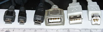
- Micro-B plug
- Proprietary UC-E6 connector used on many older Japanese cameras for both USB and analog AV output
- Mini-B plug
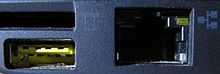
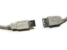
- Standard-A receptacle (non-compliant because USB does not allow extension cables [ 1 ] )
- Standard-A plug
- Standard-B plug


- Power (V BUS , 5 V)
- Data− (D−)
- Data+ (D+)
- ID (On-The-Go)
- GND
- SuperSpeed transmit− (SSTx−)
- SuperSpeed transmit+ (SSTx+)
- GND
- SuperSpeed receive− (SSRx−)
- SuperSpeed receive+ (SSRx+)