Operational amplifier
If predictable operation is desired, negative feedback is used, by applying a portion of the output voltage to the inverting input.
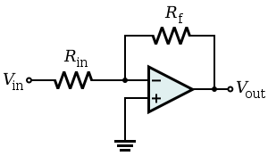
In the non-inverting amplifier on the right, the presence of negative feedback via the voltage divider Rf, Rg determines the closed-loop gain ACL = Vout / Vin.
An ideal op amp is usually considered to have the following characteristics:[5][6][7] These ideals can be summarized by the two golden rules: The first rule only applies in the usual case where the op amp is used in a closed-loop design (negative feedback, where there is a signal path of some sort feeding back from the output to the inverting input).
Generally, at room temperature, with a fairly large signal, and limited bandwidth, FET and MOSFET op amps now offer better performance.
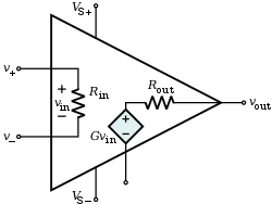
The input stage consists of a cascaded differential amplifier (outlined in dark blue) followed by a current-mirror active load.
The first stage consists of the matched NPN emitter follower pair Q1, Q2 that provide high input impedance.
[nb 6] Thus, a small-signal differential current in Q3 versus Q4 appears summed (doubled) at the base of Q15, the input of the voltage gain stage.
At the same time, the magnitude of the quiescent current is relatively insensitive to the characteristics of the components Q1–Q4, such as hfe, that would otherwise cause temperature dependence or part-to-part variations.
Introducing the transconductance of Q1, gm = hfe / hie, the (small-signal) current at the base of Q15 (the input of the voltage gain stage) is Vingm / 2.
On the other hand, a small positive change in voltage at the non-inverting input (Q1 base) drives this transistor into conduction, reflected in an increase in current at the collector of Q3.
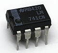
The innovation of the Fairchild μA741 was the introduction of frequency compensation via an on-chip (monolithic) capacitor, simplifying application of the op amp by eliminating the need for external components for this function.
The 30 pF capacitor stabilizes the amplifier via Miller compensation and functions in a manner similar to an op-amp integrator circuit.
While the 741 was historically used in audio and other sensitive equipment, such use is now rare because of the improved noise performance of more modern op amps.
Specific commercially available op amps and other components are then chosen that meet the design criteria within the specified tolerances at acceptable cost.
A prototype is then built and tested; additional changes to meet or improve the specification, alter functionality, or reduce the cost, may be made.
A zero voltage level detector (Ei = 0) can convert, for example, the output of a sine-wave from a function generator into a variable-frequency square wave.
Another typical configuration of op amps is with positive feedback, which takes a fraction of the output signal back to the non-inverting input.
is very large, this simplifies to The non-inverting input of the operational amplifier needs a path for DC to ground; if the signal source does not supply a DC path, or if that source requires a given load impedance, then the circuit will require another resistor from the non-inverting input to ground.
As with the non-inverting amplifier, we start with the gain equation of the op amp: This time, V− is a function of both Vout and Vin due to the voltage divider formed by Rf and Rin.
That is, the capacitive component of the input impedance inserts a DC zero and a low-frequency pole that gives the circuit a bandpass or high-pass characteristic.
The constant operating potential typically results in distortion levels that are lower than those attainable with the non-inverting topology.
[citation needed] Most single, dual and quad op amps available have a standardized pin-out which permits one type to be substituted for another without wiring changes.
A specific op amp may be chosen for its open loop gain, bandwidth, noise performance, input impedance, power consumption, or a compromise between any of these factors.
The differential input made a whole range of new functionality possible, but it would not be used for a long time due to the rise of the chopper-stabilized amplifier.
This vastly improved the gain of the op amp while significantly reducing the output drift and DC offset.
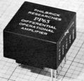
In 1953, vacuum tube op amps became commercially available with the release of the model K2-W from George A. Philbrick Researches, Incorporated.
Two nine-pin 12AX7 vacuum tubes were mounted in an octal package and had a model K2-P chopper add-on available that would effectively "use up" the non-inverting input.
[citation needed] These packages were crucially important as they made the operational amplifier into a single black box which could be easily treated as a component in a larger circuit.
Issues such as an uneven supply voltage, low gain and a small dynamic range held off the dominance of monolithic op amps until 1965 when the μA709[25] (also designed by Bob Widlar) was released.
supply voltages in analog circuits have decreased (as they have in digital logic) and low-voltage op amps have been introduced reflecting this.