Plotting board
A plotting board was a mechanical device used by the U.S. Army Coast Artillery Corps as part of their fire control system to track the observed course of a target (typically a moving ship), project its future position, and derive the uncorrected data[note 1] on azimuth (or direction) and range needed to direct the fire of the guns of a battery to hit that target.
Plotting boards of this sort were first employed by the Coast Artillery[note 2] around 1905, and were the primary means of calculating firing data until WW2.
Towards the end of WW2 these boards were largely replaced by radar and electro-mechanical gun data computers, and were relegated to a back-up role.
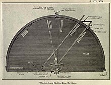
[4] The Whistler-Hearn plotting board (see Plate XXV at right, top) was a semicircular wooden table about 7.5 feet in diameter with a mechanism on top that could be configured to represent the geography of the harbor area in which it was used, including the locations of the base end stations that observed targets for the gun battery it controlled and the location of the gun(s) of that battery.
The mechanism of radial arms and adjustable slides, arcs, and gears converted observations that had been telephoned in from the base end stations into firing data for the guns.
[3] After these adjustments, the plotting board represented a true analog of the harbor being defended (see figure at left above) and was ready for use in fire control.
[note 7] If one of the two base end stations was put out of action (due to enemy fire or a communications casualty) the battery would have to switch to a less precise method of fire control, such as vertical base observation (using a depression position finder), the use of a self-contained rangefinder instrument, or aiming its guns directly, using their own telescopic sights.
[note 10] Observers in the two widely separated base end stations for the chosen battery tracked the target, using either azimuth scopes or more sophisticated depression position finders (DPFs).
Hundredths of a degree were indicated by turning the geared index disk, a wheel with 100 teeth that enabled adjusting the angle of the arm very precisely.
[note 11] After tracking a target for a short time, there would a string of plotted positions indicated on the board (e.g., the blue circles shown in Figure 1 above, left).
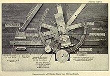
To see how this and further steps in the fire control process were accomplished, our attention shifts to the mechanisms of the gun arm center, shown in Plate XXVI at the right.
[2] Plate XXVI shows the gun arm (although the range scale on its edge is not visible), which points here toward the top of the photo (in the 11:30 position).
[2] Corrections in range were applied by turning the knob attached to a gear wheel (labeled "pinion" in Plate XXVI) at the center of the correction box, which slid the gun arm towards its circumference or back, with the adjustments indicated by index numbers visible through the window to the left of the pinion.