Cylinder head porting
Cylinder heads, as manufactured, are usually suboptimal for racing applications due to being designed for maximum durability.
When a modification is decided upon through testing with an air flow bench, the original port wall material can be reshaped by hand with die grinders or by numerically controlled milling machines.
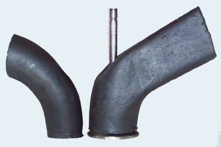
The Ford two-liter F2000 engine in stock trim equipped with the head shown above was capable of delivering 115 horsepower at 5500 rpm for a BMEP of 136 psi.
This aftermarket Pro Stock racing head was used in an engine capable of 1300 horsepower at 9500 rpm with a BMEP of 238 psi.
That is, any time a change occurs in the cylinder – whether positive or negative – such as when the piston reaches maximum speed.
For normal automotive design this point is almost always between 69 and 79 degrees ATDC, with higher rod ratios favoring the later position.
At first glance this wave travel might seem to be blindingly fast and not very significant but a few calculations show the opposite is true.
In an intake runner at room temperature the sonic speed is about 1,100 feet per second (340 m/s) and traverses a 12-inch (300 mm) port/runner in 0.9 milliseconds.
The signals coming from the piston dome, after the initial runner flow has been established, must fight upstream against whatever velocity has been developed at that instant, delaying it further.
Large portions of it bounce off the rest of the combustion chamber and resonate inside the cylinder until an average pressure is reached.
When the valve closes, it causes a pile up of gas giving rise to a strong positive wave that must travel up the runner.
Note how the suction wave during cylinder filling is delayed even more by having to fight upstream against the inrushing air and the fact that the piston is further down the bore, increasing the distance.
When it does work, it is possible to see volumetric efficiencies of 140%, similar to that of a decent supercharger, but it only occurs over a limited RPM range.
In fact, within intake systems, the surface is usually deliberately textured to a degree of uniform roughness to encourage fuel deposited on the port walls to evaporate quickly.
The complex and sensitive shapes required in porting necessitate a good degree of artistic skill with a hand tool.
5-Axis CNC controls using specialized fixtures like tilting rotary tables allow the cutting tool full access to the entire port.
The combination of CNC and CAM software give the porter full control over the port shape and surface finish.
Successfully optimizing ports requires an air flow bench, a thorough knowledge of the principles involved, and engine simulation software.