Reflector sight
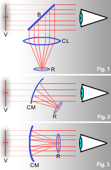
[1][2] These sights work on the simple optical principle that anything at the focus of a lens or curved mirror (such as an illuminated reticle) will appear to be sitting in front of the viewer at infinity.
The image is reflected off some form of angled beam splitter or the partially silvered collimating curved mirror itself so that the observer (looking through the beam splitter or mirror) will see the image at the focus of the collimating optics superimposed in the sight's field of view in focus at ranges up to infinity.
A more compact type replaces the lens/beam splitter configuration with a half silvered or dichroic curved collimating mirror set at an angle that performs both tasks of focusing and combining the image of an offset reticle.
[6] The viewing portion of a reflector sight does not use any refractive optical elements, it is simply a projected reticle bounced off a beam splitter or curved mirror right into the users eye.
[7] The idea of a reflector sight originated in 1900 with Irish optical designer and telescope maker Howard Grubb in patent No.12108.
[17][18] The reflector sight's single, parallax-free virtual image, in focus with the target, removes this aiming problem, helping poor, average, and expert shooters alike.
[19] Some manufacturers of small arms sights also make models with the optical collimator set at a finite distance.
Since reflector sights are not dependent on eye relief, they can theoretically be placed in any mechanically-convenient mounting position on a weapon.
The optical nature of the reflector sight meant it was possible to feed other information into field of view, such as modifications of the aiming point due to deflection determined by input from a gyroscope.
[21] 1939 saw the development by the British of the first of these gyro gunsights, reflector sights adjusted by gyroscope for the aircraft's speed and rate of turn, enabling the display of a lead-adjusted sighting reticle that lagged the actual "boresight" of the weapon(s), allowing the boresight to lead the target in a turn by the proper amount for an effective strike[21] As reflector sight designs advanced after World War II, giving the pilot more and more information, they eventually evolved into the head-up display (HUD).
[22] The illuminated reticle was eventually replaced by a video screen at the focus of the collimating optics that not only gave a sighting point and information from a lead-finding computer and radar, but also various aircraft indicators (such as an artificial horizon, compass, altitude and airspeed indicators), facilitating the visual tracking of targets or the transition from instrument to visual methods during landings.
[27] The typical configuration for this sight is a compact curved mirror reflector design with a red light-emitting diode (LED) at its focus.
A 5 moa (1.5 milliradian) dot is small enough not to obscure most targets, and large enough to quickly acquire a proper "sight picture".
For many types of action shooting, a larger dot has traditionally been preferred; 7, 10, 15 or even 20 moa (2, 3, 4.5 or 6 mil) have been used; often these will be combined with horizontal and/or vertical lines to provide a level reference.
Most sights have either active or passive adjustments for the reticle brightness, which help the shooter adapt to different lighting conditions.
Modern optical reflector sights designed for firearms and other uses fall into two housing-configurations: "tubed" and "open".
[32] Reflector sights are also used in the entertainment industry in productions such as live theater on "Follow Spot" spotlights.
Sights such as Telrad's adapted for use and the purpose built Spot Dot[33] allow the spotlight operator to aim the light without turning it on.