Vapor-compression refrigeration
The selection of working fluid has a significant impact on the performance of the refrigeration cycles and as such it plays a key role when it comes to designing or simply choosing an ideal machine for a certain task.
These refrigerants were commonly used due to their superior stability and safety properties: they were not flammable at room temperature and atmospheric pressure, nor obviously toxic as were the fluids they replaced, such as sulfur dioxide.
In the stratosphere, substances like CFCs and HCFCs break up due to UV radiation, releasing their chlorine free-radicals.
This causes severe damage to the ozone layer that shields the Earth's surface from the Sun's strong UV radiation and has been shown to lead to increased rates of skin cancer.
Newer refrigerants that have reduced ozone depletion effects compared to CFCs have replaced most CFC use.
[3] These have similar efficiencies[citation needed] compared to existing CFC- and HFC-based compounds, and have many orders of magnitude lower global warming potential.
In industrial settings ammonia, as well as gasses like ethylene, propane, iso-butane and other hydrocarbons are commonly used (and have their own R-x customary numbers), depending on required temperatures and pressures.
Many of these gases are flammable, explosive, or toxic; making their use restricted (i.e. well-controlled environment by qualified personnel, or a very small amount of refrigerant used).
HFOs which can be considered to be HFCs with some carbon-carbon bonds being double bounds, do show promise of lowering GWP so little to be of no further concern.
In the meantime, various blends of existing refrigerants are used to achieve the required properties and efficiency, at a reasonable cost and lower GWP.
The thermodynamics of the vapor compression cycle can be analyzed on a temperature versus entropy diagram as depicted in Figure 2.
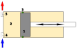
Between points 4 and 5, the subcooled liquid refrigerant passes through the expansion valve and undergoes an abrupt decrease of pressure.
Open compressor motors are typically air-cooled and can be fairly easily exchanged or repaired without degassing of the refrigeration system.
In order to lubricate the moving parts of the compressor, oil is added to the refrigerant during installation or commissioning.
Avoiding the need for oil lubrication and the design requirements and ancillaries associated with it, simplifies the design of the refrigerant system, increases the heat transfer coefficient in evaporators and condensers, eliminates the risk of refrigerant being contaminated with oil, and reduces maintenance requirements.
In countries adhering to the Montreal Protocol, HCFCs are due to be phased out and are largely being replaced by ozone-friendly HFCs.
HFCs also have an extremely large global warming potential, because they remain in the atmosphere for many years and trap heat more effectively than carbon dioxide.
For example, Coca-Cola's vending machines at the 2006 FIFA World Cup in Germany used refrigeration utilizing CO2.
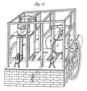
[12] In 1805, the American inventor Oliver Evans described a closed vapor-compression refrigeration cycle for the production of ice by ether under vacuum.
[13] In 1834, an American expatriate to Great Britain, Jacob Perkins, built the first working vapor-compression refrigeration system in the world.
[15] A similar attempt was made in 1842, by American physician, John Gorrie,[16] who built a working prototype, but it was a commercial failure.
The first practical vapor compression refrigeration system was built by James Harrison, a British journalist who had emigrated to Australia.
Harrison also introduced commercial vapor-compression refrigeration to breweries and meat packing houses and, by 1861, a dozen of his systems were in operation in Australia and England.
Carl von Linde, an engineering professor at the Technological University Munich in Germany, patented an improved method of liquefying gases in 1876.
His new process made possible using gases such as ammonia, sulfur dioxide SO2, and methyl chloride (CH3Cl) as refrigerants and they were widely used for that purpose until the late 1920s.


screw compressor