Railroad switch
As iron-railed plateways became more common in the eighteenth century, cast iron components were made to build switches with check rails.
[3] In 1797, John Curr described the system that he developed which used a single iron blade, hinged on a vertical pin that was tapered to lie against the plateway.
[6] Prior to the widespread availability of electricity, switches at heavily traveled junctions were operated from a signal box constructed near the tracks through an elaborate system of rods and levers.
Eventually, mechanical systems known as interlockings were introduced to make sure that a signal could only be set to allow a train to proceed over points when it was safe to do so.
On some low-traffic branch lines, in self-contained marshalling yards, or on heritage railways, switches may still have the earlier type of interlocking.
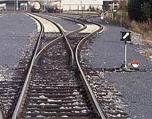
In a trailing-point movement (running through the switch in the wrong direction while they are set to turn off the track), the flanges on the wheels will force the points to the proper position.
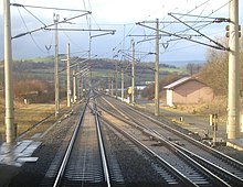
On European high-speed lines, it is not uncommon to find switches where a speed of 200 km/h (124 mph) or more is allowed on the diverging branch.
Such approaches however, may not always be effective for extreme climates since these chemicals will be washed away over time, especially for heavily thrown switches that experience hundreds of throws daily.
In the United Kingdom points and crossings using chaired bullhead rail would be referred to using a letter and number combination.
In professional parlance, the term refers only to the movable rails and the entire mechanism is named turnout or points and crossings.
It can be assembled out of several appropriately cut and bent pieces of rail or can be a single casting of manganese steel.
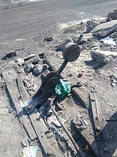
There is also usually some kind of manual handle for operating the switch in emergencies, such as power failures, or for maintenance purposes.
The lever and its accompanying hardware is usually mounted to a pair of long ties (sleepers) that extend from the switch at the points.
In the United Kingdom, FPLs were common from an early date, due to laws being passed which forced the provision of FPLs for any routes traveled by passenger trains – it was, and still is, illegal for a passenger train to make a facing move over points without them being locked, either by a point lock, or temporarily clamped in one position or another.
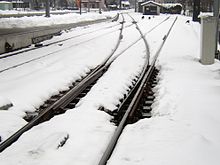
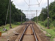
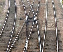
These compact (albeit complex) switches usually are found only in locations where space is limited, such as station throats (i.e. approaches) where a few main lines spread out to reach any of numerous platform tracks.
Likewise, it is called Engels(e) Wissel in Dutch and, occasionally, Engländer ("english one", literally "Englishman") in German.
This is normally used to allow access to sidings and improve safety by avoiding having switch blades facing the usual direction of traffic.
Due to the inherent complexity of the arrangement, interlaced turnouts are normally only used in locations where space is exceptionally tight, such as station throats or industrial areas within large cities.
Run-off points are used to protect main lines from stray or runaway cars, or from trains passing signals set at danger.
In some cases, catch points lead into a sand drag to safely stop the runaway vehicle, which may be traveling at speed.
They can be set to allow a train to pass safely in the downhill direction using a lever or other mechanism to override the spring for a short time.
At dual gauge turntables, a similar arrangement is used to move the narrow-gauge track from one side to a central position.
The Dolderbahn switch works by bending all three rails, an operation that is performed every trip as the two trains pass in the middle.
These would also often utilize swingnose crossings at the outer ends to ensure complete wheel support in the same way as provided on shallow angle turnouts.
This can be seen in how, under examination, the wing rail has a wider polished section, showing how the wheel load is transferred across the gap.
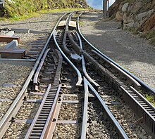
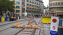
On streetcar (tram) systems using grooved rails, if the wheels on both sides of the car are connected by a rigid solid axle, only one switchpoint is needed to steer it onto one or the other track.
Some low floor streetcar designs use split axles (a separate half-axle for the wheel on each side of the car).
They are used on the Pilatus Cog Railway to allow up-bound and down-bound trains to pass each other on a grade while sharing the remainder of the single track.
These are known as Kletterweichen [de] or Auflegeweichen in German, aiguillages californiens in French, and oplegwissels [nl], klimwissels or Californische wissels in Dutch.
In North America, turnouts are rated numerically, which represents the ratio of divergence per length as measured at the frog.