Voltage regulator
Any difference is amplified and used to control the regulation element in such a way as to reduce the voltage error.
The magnetic field produced by the current attracts a moving ferrous core held back under spring tension or gravitational pull.
As voltage decreases, so does the current, releasing spring tension or the weight of the core and causing it to retract.
If the mechanical regulator design is sensitive to small voltage fluctuations, the motion of the solenoid core can be used to move a selector switch across a range of resistances or transformer windings to gradually step the output voltage up or down, or to rotate the position of a moving-coil AC regulator.
Early automobile generators and alternators had a mechanical voltage regulator using one, two, or three relays and various resistors to stabilize the generator's output at slightly more than 6.7 or 13.4 V to maintain the battery as independently of the engine's rpm or the varying load on the vehicle's electrical system as possible.
The relay(s) modulated the width of a current pulse to regulate the voltage output of the generator by controlling the average field current in the rotating machine which determines strength of the magnetic field produced which determines the unloaded output voltage per rpm.
A generator uses a mechanical commutator, graphite brushes running on copper segments, to convert the AC produced into DC by switching the external connections at the shaft angle when the voltage would reverse.
Where a generator is connected in parallel with other sources such as an electrical transmission grid, changing the excitation has more of an effect on the reactive power produced by the generator than on its terminal voltage, which is mostly set by the connected power system.
[2] AVRs on grid-connected power station generators may have additional control features to help stabilize the electrical grid against upsets due to sudden load loss or faults.
This type of regulator can be automated via a servo control mechanism to advance the movable coil position in order to provide voltage increase or decrease.
The ferroresonant approach is attractive due to its lack of active components, relying on the square loop saturation characteristics of the tank circuit to absorb variations in average input voltage.
Saturating transformers provide a simple rugged method to stabilize an AC power supply.
Output power factor remains in the range of 0.96 or higher from half to full load.
The current-limiting capability also becomes a handicap when a CVT is used in an application with moderate to high inrush current, like motors, transformers or magnets.
In this case, the CVT has to be sized to accommodate the peak current, thus forcing it to run at low loads and poor efficiency.
It accepts 100% single-phase switch-mode power-supply loading without any requirement for derating, including all neutral components.
Drawbacks of CVTs are their larger size, audible humming sound, and the high heat generation caused by saturation.
Shunt regulators are often (but not always) passive and simple, but always inefficient because they (essentially) dump the excess current which is not available to the load.
Linear regulators are also classified in two types: In the past, one or more vacuum tubes were commonly used as the variable resistance.
Switching regulators are also able to generate output voltages which are higher than the input, or of opposite polarity—something not possible with a linear design.
Hence the power transmitted across the pass device is in discrete pulses rather than a steady current flow.
Again when the pass device is in saturation, a negligible voltage drop appears across it and thus dissipates only a small amount of average power, providing maximum current to the load.
Switched mode regulators rely on pulse-width modulation to control the average value of the output voltage.
Unlike linear regulators, these usually require an inductor that acts as the energy storage element.
[4][5] The IC regulators combine the reference voltage source, error op-amp, and pass transistor with short-circuit current limiting and thermal-overload protection.
An efficient way of creating a variable-voltage, accurate output power supply is to combine a multi-tapped transformer with an adjustable linear post-regulator.
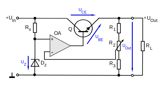
In the simplest case a common base amplifier is used with the base of the regulating transistor connected directly to the voltage reference: A simple transistor regulator will provide a relatively constant output voltage Uout for changes in the voltage Uin of the power source and for changes in load RL, provided that Uin exceeds Uout by a sufficient margin and that the power handling capacity of the transistor is not exceeded.
On the other hand, lower values of Rv lead to higher power dissipation in the diode and to inferior regulator characteristics.