Solar-cell efficiency
Solar-cell efficiency is the portion of energy in the form of sunlight that can be converted via photovoltaics into electricity by the solar cell.
[1] The global regions that have high radiation levels throughout the year are the middle east, Northern Chile, Australia, China, and Southwestern USA.
[1][2] In a high-yield solar area like central Colorado, which receives annual insolation of 2000 kWh/m2/year,[3] a panel can be expected to produce 400 kWh of energy per year.
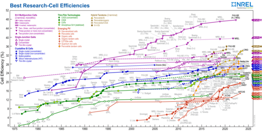
The record in real-world conditions is held by NREL, who developed triple junction cells with a tested efficiency of 39.5%.
[10][11] The factors affecting energy conversion efficiency were expounded in a landmark paper by William Shockley and Hans Queisser in 1961.
They also considered the more relevant problem of maximizing the power output for a stack being illuminated from all directions by 6000 K blackbody radiation.
The maximum theoretical efficiency calculated is 86.8% for a stack of an infinite number of cells, using the incoming concentrated sunlight radiation.
Traditional single-junction cells with an optimal band gap for the solar spectrum have a maximum theoretical efficiency of 33.16%, the Shockley–Queisser limit.
Quantum efficiency refers to the percentage of photons that are converted to electric current (i.e., collected carriers) when the cell is operated under short circuit conditions.
The "external" quantum efficiency of a silicon solar cell includes the effect of optical losses such as transmission and reflection.
Since some wavelengths are absorbed more effectively than others, spectral measurements of quantum efficiency can yield valuable information about the quality of the semiconductor bulk and surfaces.
By increasing the resistive load on an irradiated cell continuously from zero (a short circuit) to a very high value (an open circuit) one can determine the maximum power point, the point that maximizes V×I; that is, the load for which the cell can deliver maximum electrical power at that level of irradiation.
Maximum power (with 45 °C cell temperature) is typically produced with 75% to 80% of the open-circuit voltage (0.43 V in this case) and 90% of the short-circuit current.
Vendors who rate their solar cell "power" only as VOC x ISC, without giving load curves, can be seriously distorting their actual performance.
[20] Recently, new research to remove dust from solar panels has been developed by utilizing electrostatic cleaning systems.
In such systems, an applied electrostatic field at the surface of the solar panels causes the dust particles to move in a "flip-flop" manner.
[22] The fill factor is directly affected by the values of the cell's series, shunt resistances and diodes losses.
These so-called "concentrator systems" have only begun to become cost-competitive as a result of the development of high efficiency GaAs cells.
A common method used to express economic costs is to calculate a price per delivered kilowatt-hour (kWh).
[30][32][33] Generally, thin-film technologies—despite having comparatively low conversion efficiencies—achieve significantly shorter energy payback times than conventional systems (often < 1 year).
In this meta study, which uses an insolation of 1,700 kWh/m2/year and a system lifetime of 30 years, mean harmonized EROIs between 8.7 and 34.2 were found.
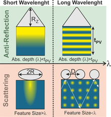
Such light-trapping scheme is accomplished by the deviation of the light rays from the incident direction, thereby increasing their path length in the cells' absorber.
[41] When applied in the devices' front these structures can act as geometric anti-reflective coatings, simultaneously reducing the reflection of out-going light.
[42] Aluminium absorbs only ultraviolet radiation, and reflects both visible and infra-red light, so energy loss is minimized.
[43] Anti-reflective coatings are engineered to reduce the sunlight reflected from the solar cells, therefore enhancing the light transmitted into the photovoltaic absorber.
[45] It was reported that utilizing this sort of surface architecture minimizes the reflection losses by 25%, converting the additional captured photon to a 12% increase in a solar cell's energy.
Concomitantly, they promote light scattering effects that further enhance the absorption, particularly of the longer wavelength sunlight photons.
The silica layer acts as a thermal black body, which emits heat as infrared radiation into space, cooling the cell up to 13 °C.
Although not constituting a direct strategy to improve efficiency, thin film materials show a lot of promise for solar cells in terms of low costs and adaptability to existing structures and frameworks in technology.
Perovskites demonstrate a remarkable ability to efficiently capture and convert blue light, complementing silicon, which is particularly adept at absorbing red and infrared wavelengths.