UML state machine
UML statecharts introduce the new concepts of hierarchically nested states and orthogonal regions, while extending the notion of actions.
Many software systems are event-driven, which means that they continuously wait for the occurrence of some external or internal event such as a mouse click, a button press, a time tick, or an arrival of a data packet.
The concept of a FSM is important in event-driven programming because it makes the event handling explicitly dependent on both the event-type and on the state of the system.
[5] Conversely, using event-driven programming without an underlying FSM model can lead programmers to produce error prone, difficult to extend and excessively complex application code.
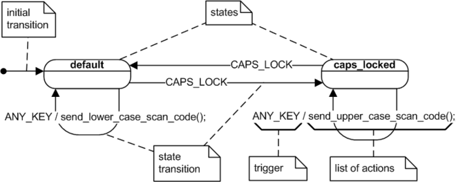
The transitions, represented as arrows, are labeled with the triggering events followed optionally by the list of executed actions.
The initial transition originates from the solid circle and specifies the default state when the system first begins.
Though the traditional FSMs are an excellent tool for tackling smaller problems, it's also generally known that they tend to become unmanageable, even for moderately involved systems.
For example, if you try to represent the behavior of a simple pocket calculator with a traditional FSM, you'll immediately notice that many events (e.g., the Clear or Off button presses) are handled identically in many states.
A conventional FSM shown in the figure below, has no means of capturing such a commonality and requires repeating the same actions and transitions in many states.
Obviously, these features are very interesting to software developers, because only they make the whole state machine approach truly applicable to real-life problems.
This state machine will attempt to handle any event in the context of the substate, which conceptually is at the lower level of the hierarchy.
However, composite states don't simply hide complexity; they also actively reduce it through the powerful mechanism of hierarchical event processing.
[11] Orthogonal regions address the frequent problem of a combinatorial increase in the number of states when the behavior of a system is fragmented into independent, concurrently active parts.
The use of orthogonal regions allows the mixing of independent behaviors as a Cartesian product to be avoided and, instead, for them to remain separate, as shown in Figure 4.
Note that if the orthogonal regions are fully independent of each other, their combined complexity is simply additive, which means that the number of independent states needed to model the system is simply the sum k + l + m + ..., where k, l, m, ... denote numbers of OR-states in each orthogonal region.
Among these rich sets of (sometimes complex) mechanisms, perhaps the most important feature is that orthogonal regions can coordinate their behaviors by sending event instances to each other.
[12] The UML specification requires only that the designer does not rely on any particular order for event instances to be dispatched to the relevant orthogonal regions.
The value of entry and exit actions is that they provide means for guaranteed initialization and cleanup, very much like class constructors and destructors in Object-oriented programming.
Of course, such behavior could be modeled by adding appropriate actions (disabling the heater and turning on the light) to every transition path leading to the "door_open" state (the user may open the door at any time during "baking" or "toasting" or when the oven is not used at all).
More importantly, such an approach leaves the design error-prone during subsequent amendments to behavior (e.g., the next programmer working on a new feature, such as top-browning, might simply forget to disable the heater on transition to "door_open").
Entry and exit actions allow implementation of desired behavior in a safer, simpler, and more intuitive way.
The semantics of exit actions guarantees that, regardless of the transition path, the heater will be disabled when the toaster is not in the "heating" state.
The execution of exit actions, which corresponds to destructor invocation, proceeds in the exact reverse order (bottom-up).
Internal transitions inherited from superstates at any level of nesting act as if they were defined directly in the currently active state.
The UML specification prescribes that taking a state transition involves executing the actions in the following predefined sequence (see Section 14.2.3.9.6 of OMG Unified Modeling Language (OMG UML)[1]): The transition sequence is easy to interpret in the simple case of both the main source and the main target nesting at the same level.
If the main target state is composite, the UML semantics prescribes to "drill" into its submachine recursively using the local initial transitions.
The UML specification[1] makes this distinction apparent by clearly separating state machine semantics from the notation.
Any nontrivial state machine requires a large amount of textual information (e.g., the specification of actions and guards).
Similarly, statechart diagrams require a lot of plumbing gear (pseudostates, like joins, forks, junctions, choicepoints, etc.)
In other words, these elements of the graphical notation do not add much value in representing flow of control as compared to plain structured code.