Synchro
A synchro (also known as selsyn and by other brand names) is, in effect, a transformer whose primary-to-secondary coupling may be varied by physically changing the relative orientation of the two windings.
[2] Smaller synchros are still used to remotely drive indicator gauges and as rotary position sensors for aircraft control surfaces, where the reliability of these rugged devices is needed.
Large synchros were used on naval warships, such as destroyers, to operate the steering gear from the wheel on the bridge.
In a torque system, a synchro will provide a low-power mechanical output sufficient to position an indicating device, actuate a sensitive switch or move light loads without power amplification.
In a motion picture interlock system, a large motor-driven distributor can drive as many as 20 machines, sound dubbers, footage counters, and projectors.
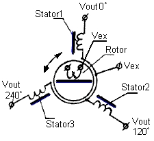
Single phase units have five wires: two for an exciter winding (typically line voltage) and three for the output/input.
These three are bussed to the other synchros in the system, and provide the power and information to align the shafts of all the receivers.
CTs have high-impedance stators and draw much less current than ordinary synchro receivers when not correctly positioned.
The "spool" is the secondary winding's core, its flanges are the poles, and its coupling does not vary significantly with rotor position.
The primary winding is similar, surrounded by its magnetic core, and its end pieces are like thick washers.
For high accuracy in gun fire control and aerospace work, so called multi-speed synchro data links were used.
So called multispeed synchros have stators with many poles, so that their output voltages go through several cycles for one physical revolution.
There are synchro-like devices called transolvers, somewhat like differential synchros, but with three-lead rotors and four-lead stators.