TXE
When World War II ended, the UK telephone exchange suppliers supported the GPO's decision to stay with Strowger until a viable electronic system became available.
This lab was headed by John Flood, who had been a founder member of Tommy Flowers' electronic switching team at Dollis Hill.
At this time, in the US, Bell Labs were developing a system based on electronically controlled reed relays, and this looked promising.
STC built the common control, AEI the switching and scanners, line scanning and test console, and AT&E the dialling capturing equipment (registers) and the incoming and outgoing junctions.
A local register would provide dial tone to the subscriber, wait for the first dialled digit, and then apply to the translator to see what action was required.
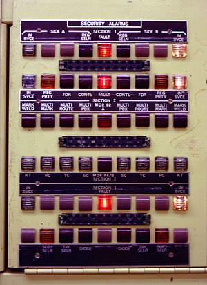
Periodically over some weeks, the mercury would migrate to the point of contact of the blades, leaving a mercuric bead giving “ON” and both A and B sides into service.
In periods of very low traffic, there would typically be fewer than eight call set-up attempts on the exchange in eight minutes and this would have prevented the above security system from working.
Unlike the preceding rural Strowger exchanges (UAX 13s and smaller) the TXE2s were equipped with an uninterruptible power supply with auto-starting diesel generators.
As the TXE2 call-set-up time was some 50 milliseconds, this design requirement was just met, but even so, the overall capacity of the system was determined by the probability of an incoming call being delayed too long in its initial connection to a register.
These faults were very difficult to locate and in the end, the problems were only resolved by a fairly substantial re-reeding programme carried out on the common-control units of the early Plessey exchanges.
Once the teething troubles had been largely dealt with, which was not until about 1974, the TXE2s realised more of their expected benefits and it was eventually not uncommon for one Technical Officer to maintain the operation of three of these exchanges, serving perhaps some 5,000–6,000 customers in total.
It did, however, take a lot of subsequent work by the switch maintenance Technical Officers to get the exchange up to an acceptable standard of service, as it had been standing idle for several years.
The takeover bid was successful and GEC decided that they preferred the crossbar system to TXE3 and promptly cancelled the contract to supply TXE3 to the BPO.
The MCU operated in accordance with an instruction program stored in the form of a number of wires threading a bank of magnetic cores.
This information was returned to the Route Choice Unit, which then identified those link circuits, which were available to both peripheral terminals, and selected the most suitable, according to predetermined rules chosen to make maximum use of the network.
In every case the MCU would decide, in accordance with its program instructions, what connection pattern was appropriate in the circumstances indicated and issue orders for setting the paths.
Within each MCU information was handled in a "two-out-of-five" code which enabled errors to be detected, and the output of the program store was duplicated to give additional protection.
The TXE4 was a cost reduced development of the TXE3 system and catered for up to 40,000 subscribers with over 5,000 erlangs of both-way traffic and was normally staffed by several Technical Officers (TO).
It was built at the STC Southgate factory in north London and used reed relays as the switching medium which proved reliable in service.
The information stored was the class of service (COS) i.e. PBX, coin collecting box (CCB) or single line, followed by the directory number.
When a subscriber lifted their handset it sent a pulse down this wire, which was picked up by a 156 ms scanner, which set up a path through the reed relays to a register.
The MCUs had core memory to hold the dialled digits from all the Registers and also had other storage to manipulate call set-up information.
The difficulty of manually spotting trends brought an attempt to take the paper tape that the teleprinter produced, as well as the print, and automatically analyse it.
It had the same switching as TXE4 but a redesigned common control, using integrated circuits (including microprocessors) to achieve significant size and cost reductions.
This allowed for changes to exchange data i.e. customer information to be made by keyboard instead of by manually threading jumpers through Dimond rings.
The enhancement features were implemented on additional dedicated processing modules interconnected by an Ethernet backbone with the MCU and SPU processors.
The TXE4E replaced the ten Miniature Threaded Wire Stores (MTWS) of the TXE4 with two units, each containing six chips which were removable and re-programmed with a separate computer.
Tariff changes for the eight million customers could be built and implemented by one person following the introduction of a centralised data management tool.
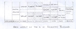
It was never used for its intended purpose but merely acted as the front end to incoming junction calls at Leighton Buzzard and directing them to either the TXE1 or one of the three TXE2 exchanges, which was decided by the first dialled digit.
unit was the interface, converting information from dialled pulses, in Strowger form, to fast parallel signal conditions for the reed group-selector registers.