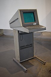
Tektronix 4010
These new graphics workstations used raster displays and dedicated screen buffers that became more affordable as solid-state memory chips became markedly cheaper.
[1] A number of graphics terminals based on this tube and others from the 600-series were developed, including the Advanced Remote Display Station from MIT's Project MAC, and the KV8I (later, KV8E) from Digital Equipment Corporation using the 11-inch diagonal 611.
[4] These were similar to the earlier third-party terminals, essentially combining one of their storage tubes with the circuitry needed to decode instructions from the host and turn those into control inputs.
However, the 4002 had the unique feature that only a portion of the screen was a storage tube, with a small section set aside for normal refresh-based drawing.
As they did not include raster scan hardware or any form of memory, refreshing this area rapidly enough to reduce flicker was up to the host computer.
The upgraded features became so widely-used that the 4014 series is sometimes considered to be a separate line from the 4010, or alternatively the canonical model for the entire family.
[9] This used a system in the monitor to scan the display line-by-line, which sent signals to the printer where a one-line-tall CRT duplicated the image on thermal paper.
[11] For storage, the systems could write out the data stream of characters as they were received from the host, allowing them to be played back locally to recreate the display.
[14] Other devices in the lineup included the 4901 and 4903 Interactive Graphic Unit, which drew crosshairs on the 4002 (this capability was built into the later models),[b] and the 4951 Joystick.
Tektronix continued selling the basic storage tubes to OEMs, the 19-inch version as the GMA101 and 102 (the former offering roughly twice the drawing speed) and the 25-inch as the GMA125.
This de facto standard for encoding graphical information was later ported to traditional video terminals using raster scan displays, although these generally offered lower resolution, perhaps half that of the 4010.
[20] Conventional modern video displays consist of a series of images, or frames, representing single snapshots in time.
One, the flood gun, provided a constant flow of low-energy electrons covering the entire screen, causing it to glow faintly.
When its beam struck the screen, it caused an effect known as photoemission that expelled electrons from the light-emitting phosphors and towards the front of the display, where they were drained away by a thin transparent electrode.
[24] The storage tube technology was vulnerable to screen burn-in, as the continuous flow of electrons illuminating a stored image gradually degraded the light-emitting phosphors over a long period of time.
To reduce the rate of display degradation, the hardware was designed to blank the electron beams after a period of inactivity on the screen.
Because the display tube itself stored the image, there was no need for any sort of auxiliary graphics memory, greatly lowering the cost of the terminal.
Early CAD systems made by companies such as Computervision took full advantage of the graphic storage capability, and were able to display arbitrarily complex designs without annoying flicker.
Tektronix introduced the write through concept for non-stored vectors, but with the terminal itself lacking any memory, the data had to be continually refreshed from the host computer.
The communications speed of the connection between the terminal and host limited the number of refreshed objects that could be supported, and was often in the range of a few dozen graphic elements.
[27] In addition to the communications card and various enhancements, an optional "Desk-Top Mounting Kit" allowed the CRT to be placed on a desk, while the electronics cart was connected to it using a cable up to 10 feet (3.0 m) away.
The 4014 terminal was normally shipped with the standard Communications Interface installed, offering an RS-232 connection, although only the most important connector pins were supported.
There was no attempt to limit drawing to within these borders, so it was up to the host software to ensure that lines remained within the margins by inserting CR/LF characters at appropriate points.
The drawing process is triggered by the reception of the low-X character, which the terminal looks for by waiting for a bit pattern that indicates it is in the proper decimal range.
This was especially useful in graph mode, as it allowed the system to draw movable objects, although at the cost of having to continually refresh them over the serial link at about 30 times a second in order to avoid flicker.
On a 4010 series terminal or 4014 without the Enhanced Graphic Module, this extra byte would then immediately be overwritten by the actual low-order address that arrived as the next character, and thus have no effect.
[40] Another feature of the Enhanced Graphic Module was circuitry that periodically interrupted the beam as it was drawing a vector, allowing the creation of dashed lines.
[41] Incremental plot, entered with the ASCII Record Separator (RS) character, replaced the normal coordinates with single-character directions.
This was especially useful for drawing control needles and similar moving displays, and greatly reduces the amount of information that has to be sent to the terminal over time.
On one hand, the bell sound appears to be overengineered: It is all-digital, generating an audio frequency from the main crystal-controlled divider chain.