Torpedo Data Computer
This unique capability of the TDC set the standard for submarine torpedo fire control during World War II.
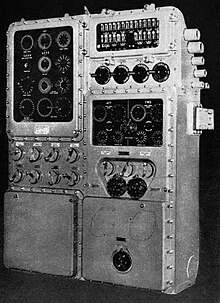
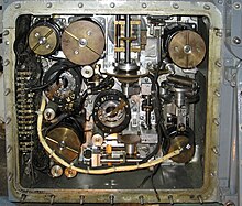
[5] The TDC was a rather bulky addition to the sub's conning tower and required two extra crewmen: one as an expert in its maintenance, the other as its actual operator.
Despite these drawbacks, the use of the TDC was an important factor in the successful commerce raiding program conducted by American submarines during the Pacific campaign of World War II.
[10] The museum also has a fully restored and functioning TDC from USS Pampanito, docked in San Francisco.
[12] In fact, two World War II-era straight running torpedoes — fired by the British nuclear-powered submarine HMS Conqueror — sank ARA General Belgrano in 1982.
During World War I, computing a target intercept course for a torpedo was a manual process where the fire control party was aided by various slide rules[13] (the U.S. examples were the Mark VIII Angle Solver (colloquially called the "banjo", for its shape), and the "Is/Was" circular sliderule (Nasmith Director), for predicting where a target will be based on where it is now and was)[14] or mechanical calculator/sights.
[19] In 1932, the Bureau of Ordnance (BuOrd) initiated development of the TDC with Arma Corporation and Ford Instruments.
[20] The first submarine designed to use the TDC was Tambor,[21] launched in 1940 with the Mark III, located in the conning tower.
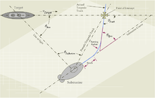
The primary role of the TDC is to determine the gyro angle setting required to ensure that the torpedo will strike the target.
During World War II, target course, range, and bearing estimates often had to be generated using periscope observations, which were highly subjective and error prone.
Some skippers, like Richard O'Kane, practiced determining the angle on the bow by looking at Imperial Japanese Navy ship models mounted on a calibrated lazy Susan through an inverted binocular barrel.
[34] The TDC needed to be positioned near other fire control equipment to minimize the amount of electromechanical interconnect.
On World War II submarines, the TDC and other fire control equipment was mounted in the conning tower, which was a very small space.
[35] The packaging problem was severe and the performance of some early torpedo fire control equipment was hampered by the need to make it small.
Providing the details as to how to correct the torpedo gyro angle calculation for ballistics and parallax is complicated and beyond the scope of this article.
Most discussions of gyro angle determination take the simpler approach of using Figure 3, which is called the torpedo fire control triangle.
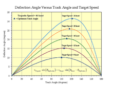
A number of publications[46][47] state the optimum torpedo track angle as 110° for a Mk 14 (46 knot weapon).
[49] As with the angle solver, the equations implemented in the position keeper can be found in the Torpedo Data Computer manual.