Truss bridge
The connected elements, typically straight, may be stressed from tension, compression, or sometimes both in response to dynamic loads.
The nature of a truss allows the analysis of its structure using a few assumptions and the application of Newton's laws of motion according to the branch of physics known as statics.
This assumption means that members of the truss (chords, verticals, and diagonals) will act only in tension or compression.
A more complex analysis is required where rigid joints impose significant bending loads upon the elements, as in a Vierendeel truss.
The ability to distribute the forces in various ways has led to a large variety of truss bridge types.
In other cases, the appearance of the structure may take on greater importance and so influence the design decisions beyond mere matters of economics.
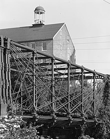
In the United States, because wood was in abundance, early truss bridges would typically use carefully fitted timbers for members taking compression and iron rods for tension members, usually constructed as a covered bridge to protect the structure.
[3]: 168 Continuous truss bridges were not very common before the mid-20th century because they are statically indeterminate, which makes them difficult to design without the use of computers.
A short selection of prefabricated modular components could be easily and speedily combined on land in various configurations to adapt to the needs at the site and allow rapid deployment of completed trusses.
In the image, note the use of pairs of doubled trusses to adapt to the span and load requirements.
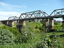
In the Pratt truss the intersection of the verticals and the lower horizontal tension members are used to anchor the supports for the short-span girders under the tracks (among other things).
A good example of the Baltimore truss is the Amtrak Old Saybrook – Old Lyme Bridge in Connecticut, United States.
It was the first successful all-metal bridge design (patented in 1852) to be adopted and consistently used on a railroad.
This type of truss is particularly suited for timber structures that use iron rods as tension members.
The Appomattox High Bridge on the Norfolk and Western Railway included 21 Fink deck truss spans from 1869 until their replacement in 1886.
This type of bridge uses a substantial number of lightweight elements, easing the task of construction.
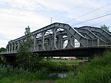
[19] One type of lenticular truss consists of arcuate upper compression chords and lower eyebar chain tension links.
Brunel's Royal Albert Bridge over the River Tamar between Devon and Cornwall uses a single tubular upper chord.
This in turn enables the truss to be fabricated on the ground and then to be raised by jacking as supporting masonry pylons are constructed.
[21] The longest surviving example is the Eldean Covered Bridge north of Troy, Ohio, spanning 224 feet (68 m).
George H. Pegram, while the chief engineer of Edge Moor Iron Company in Wilmington, Delaware, patented this truss design in 1885.
[25] The Pegram truss consists of a Parker type design with the vertical posts leaning towards the center at an angle between 60 and 75°.
The variable post angle and constant chord length allowed steel in existing bridges to be recycled into a new span using the Pegram truss design.
This design also facilitated reassembly and permitted a bridge to be adjusted to fit different span lengths.
There are twelve known remaining Pegram span bridges in the United States with seven in Idaho, two in Kansas, and one each in California, Washington, and Utah.
It was once used for hundreds of bridges in the United States, but fell out of favor in the 1930s and very few examples of this design remain.
The primary difference is the horizontal extension at the center which relies on beam action to provide mechanical stability.
It is a structure where the members are not triangulated but form rectangular openings, and is a frame with fixed joints that are capable of transferring and resisting bending moments.
While rare as a bridge type due to higher costs compared to a triangulated truss, it is commonly employed in modern building construction as it allows the resolution of gross shear forces against the frame elements while retaining rectangular openings between columns.
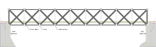
The Warren truss was patented in 1848 by James Warren and Willoughby Theobald Monzani, and consists of longitudinal members joined only by angled cross-members, forming alternately inverted equilateral triangle-shaped spaces along its length, ensuring that no individual strut, beam, or tie is subject to bending or torsional straining forces, but only to tension or compression.