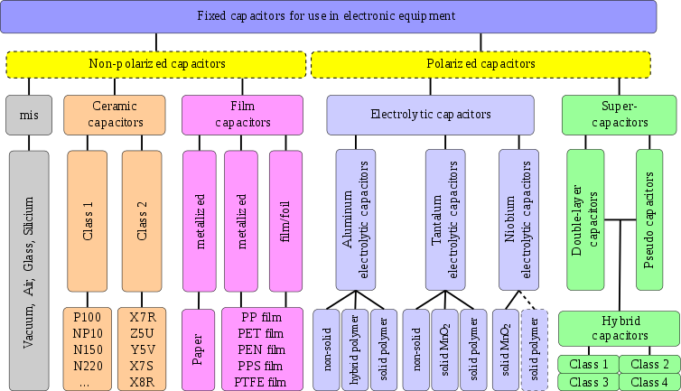
Capacitor types
Small capacitors are used in electronic devices to couple signals between stages of amplifiers, as components of electric filters and tuned circuits, or as parts of power supply systems to smooth rectified current.
Different types are used depending on required capacitance, working voltage, current handling capacity, and other properties.
Variable capacitors are made as trimmers, that are typically adjusted only during circuit calibration, and as a device tunable during operation of the electronic instrument.
They store their electrical charge statically in Helmholtz double-layers and faradaically at the surface of electrodes The most important material parameters of the different dielectrics used and the approximate Helmholtz-layer thickness are given in the table below.
Thin, mechanically flexible sheets can be wrapped or stacked easily, yielding large designs with high capacitance values.
A short view to the figures in the table above gives the explanation for some simple facts: Capacitance ranges from picofarads to more than hundreds of farads.
For capacitors, the volumetric efficiency is measured with the "CV product", calculated by multiplying the capacitance (C) by the maximum voltage rating (V), divided by the volume.
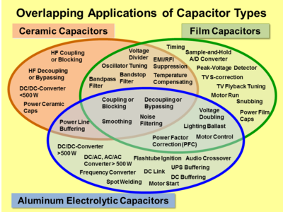
They find use as converters to change voltage, current or frequency, to store or deliver abruptly electric energy or to improve the power factor.
The permittivity of tantalum pentoxide is approximately three times higher than aluminium oxide, producing significantly smaller components.
The large capacitance per unit volume of electrolytic capacitors make them valuable in relatively high-current and low-frequency electrical circuits, e.g. in power supply filters for decoupling unwanted AC components from DC power connections or as coupling capacitors in audio amplifiers, for passing or bypassing low-frequency signals and storing large amounts of energy.
Specialized devices such as built-in capacitors with metal conductive areas in different layers of a multi-layer printed circuit board and kludges such as twisting together two pieces of insulated wire also exist.
All properties can be defined and specified by a series equivalent circuit composed out of an idealized capacitance and additional electrical components which model all losses and inductive parameters of a capacitor.
The range of units used to specify capacitor values has expanded to include everything from pico- (pF), nano- (nF) and microfarad (μF) to farad (F).
Low voltage types with highly roughened anodes display capacitance at 100 kHz approximately 10 to 20% of the value measured at 100 Hz.
Aluminum electrolytic capacitors have relatively good decoupling properties in the lower frequency range up to about 1 MHz due to their large capacitance values.
They also have significantly lower parasitic inductance, making them suitable for higher frequency applications, due to their construction with end-surface contacting of the electrodes.
Ceramic Class 1 capacitors are especially suitable for LC resonant circuits with frequencies up to the GHz range, and precise high and low pass filters.
Aluminum electrolytic capacitors, the most common type for power supplies, experience shorter life expectancy at higher ripple currents.
For film and ceramic capacitors, normally specified with a loss factor tan δ, the ripple current limit is determined by temperature rise in the body of approximately 10 °C.
For example, a capacitor can be used as the time-determining component for time relays or for storing a voltage value as in a sample and hold circuits or operational amplifiers.
Microphonics (microphony) describes how electronic components transform mechanical vibrations into an undesired electrical signal (noise).
In the reverse microphonic effect, varying the electric field between the capacitor plates exerts a physical force, turning them into an audio speaker.
[59] The voltage at the terminals generated by the dielectric absorption may in some cases possibly cause problems in the function of an electronic circuit or can be a safety risk to personnel.
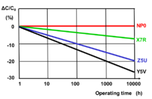
The reasons for parameter changings are different, it may be a property of the dielectric, environmental influences, chemical processes or drying-out effects for non-solid materials.
Environmental influences such as higher temperature, high humidity and mechanical stress can, over a longer period, lead to a small irreversible change in the capacitance value sometimes called aging, too.
Capacitors are reliable components with low failure rates, achieving life expectancies of decades under normal conditions.
For other conditions of applied voltage, current load, temperature, mechanical influences and humidity the FIT can recalculated with terms standardized for industrial[69] or military[70] contexts.
Capacitors may experience changes to electrical parameters due to environmental influences like soldering, mechanical stress factors (vibration, shock) and humidity.
Chemical processes weaken the oxide layer when these capacitors are not used for too long, leading to failure or poor performance such as excessive leakage.
[73] The tests and requirements to be met by capacitors for use in electronic equipment for approval as standardized types are set out in the generic specification IEC/EN 60384–1 in the following sections.


- IHP Inner Helmholtz Layer
- OHP Outer Helmholtz Layer
- Diffuse layer
- Solvated ions
- Specifically adsorptive ions (Pseudocapacitance)
- Solvent molecule