HVDC converter
Some HVDC systems take full advantage of this bi-directional property (for example, those designed for cross-border power trading, such as the Cross-Channel link between England and France).
As of 2012, both the line-commutated and voltage-source technologies are important, with line-commutated converters used mainly where very high capacity and efficiency are needed, and voltage-source converters used mainly for interconnecting weak AC systems, for connecting large-scale wind power to the grid or for HVDC interconnections that are likely to be expanded to become Multi-terminal HVDC systems in future.
[1] The most successful of these used the system invented by René Thury and were based on the principle of connecting several motor-generator sets in series on the DC side.
The best-known example was the 200 km, Lyon–Moutiers DC transmission scheme in France, which operated commercially from 1906 to 1936 transmitting power from the Moutiers hydroelectric plant to the city of Lyon.
From the 1930s onwards,[6] extensive research started to take place into static alternatives using gas-filled tubes – principally mercury-arc valves but also thyratrons – which held the promise of significantly higher efficiency.
Very small mechanical rotary convertors remained in use for niche applications in adverse environments, such as in aircraft and vehicles, as a power conversion method from batteries to the high voltages required for radio and RADAR, until the 1960s and the transistor era.
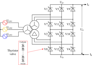
The term line-commutated indicates that the conversion process relies on the line voltage of the AC system to which the converter is connected in order to effect the commutation from one switching device to its neighbour.
[11] Line-commutated converters use switching devices that are either uncontrolled (such as diodes) or that can only be turned on (not off) by control action, such as thyristors.
Firing angle control is used to regulate the DC voltages of both ends of the HVDC system continuously in order to obtain the desired level of power transfer.
(in degrees) With a phase change only every 60°, considerable harmonic distortion is produced at both the DC and AC terminals when the six-pulse arrangement is used.
[22][23] The last operating mercury arc system (the HVDC Inter-Island link between the North and South Islands of New Zealand) was shut down in 2012.
The highest power rating of any single HVDC converter (twelve-pulse bridge) in operation was 2000 MW in 2010, on the ±660 kV Ningdong–Shandong scheme in China.
With other types of semiconductor device such as the insulated-gate bipolar transistor (IGBT), both turn-on and turn-off timing can be controlled, giving a second degree of freedom.
The additional controllability gives many advantages, notably the ability to switch the IGBTs on and off many times per cycle in order to improve the harmonic performance, and the fact that (being self-commutated) the converter no longer relies on synchronous machines in the AC system for its operation.
A voltage-sourced converter can therefore feed power to an AC network consisting only of passive loads, something which is impossible with LCC HVDC.
From the very first VSC-HVDC scheme installed (the Hellsjön experimental link commissioned in Sweden in 1997[7]) until 2012, most of the VSC HVDC systems built were based on the two level converter.
The two valves corresponding to one phase must never be turned on simultaneously, as this would result in an uncontrolled discharge of the DC capacitor, risking severe damage to the converter equipment.
Several different PWM strategies are possible for HVDC[31] but in all cases the efficiency of the two-level converter is significantly poorer than that of a LCC because of the higher switching losses.
Another disadvantage of the two-level converter is that, in order to achieve the very high operating voltages required for an HVDC scheme, several hundred IGBTs have to be connected in series and switched simultaneously in each valve.
[32] This requires specialised types of IGBT with sophisticated gate drive circuits, and can lead to very high levels of electromagnetic interference.
Such converters were used on the Murraylink project[33] in Australia and the Cross Sound Cable link in the United States.
[34] However, the modest improvement in harmonic performance came at a considerable price in terms of increased complexity, and the design proved to be difficult to scale up to DC voltages higher than the ±150 kV used on those two projects.
Another type of three-level converter, used in some adjustable-speed drives but never in HVDC, replaces the clamping diode valves by a separate, isolated, flying capacitor connected between the one-quarter and three-quarter points.
As already mentioned above, both two-level and three-level converters require simultaneous switching of hundreds of transistors connected in series and don't scale beyond ±150 kV since this task becomes too challenging.
The Modular Multi-Level Converter (MMC) was developed as a solution to this issue as transistors in it don't switch at the same time.
With a suitable number of submodules connected in series, the valve can synthesize a stepped voltage waveform that approximates very closely to a sine-wave and contains very low levels of harmonic distortion.
Balancing the voltages of each of the submodule capacitors is a significant challenge and requires considerable computing power and high-speed communications between the central control unit and the valve.
[41] A variant of the MMC, proposed by one manufacturer, involves connecting multiple IGBTs in series in each of the two switches that make up the submodule.
[38] Functionally it is exactly equivalent to the conventional half-bridge MMC in every respect except for the harmonic performance, which is slightly inferior – although still claimed to be good enough to avoid the need for filtering in most instances.
[43] These hybrid VSC systems aim to achieve the low losses and high harmonic performance of the MMC with a more compact design and greater controllability, but these concepts are still at the research stage.