Voltage multiplier
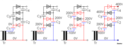
In a cascade with n stages of two diodes and two capacitors, the output voltage is equal to 2n Us - n(n+1) Uf.
In the 120 V position the input is typically configured as a full-wave voltage doubler by opening one AC connection point of a bridge rectifier, and connecting the input to the junction of two series-connected filter capacitors.
Triplers are still used in high voltage supplies such as copiers, laser printers, bug zappers and electroshock weapons.
While the multiplier can be used to produce thousands of volts of output, the individual components do not need to be rated to withstand the entire voltage range.
Note that some safety margin is needed across the relative range of voltage differences in the multiplier, so that the ladder can survive the shorted failure of at least one diode or capacitor component.
If it were odd and ended on a clamping cell the ripple voltage would be very large.
Larger capacitors in the connecting column also reduce ripple but at the expense of charging time and increased diode current.
There are, however, several important differences: To describe the ideal operation of the circuit, number the diodes D1, D2 etc.
The final diode-capacitor cell in the cascade is connected to ground rather than a clock phase and hence is not a multiplier; it is a peak detector which merely provides smoothing.
Schottky diodes are commonly used in Dickson multipliers for their low forward voltage drop, amongst other reasons.
For this reason, in the popular CMOS technology ICs the transistor which forms the basic building block of circuits is the MOSFET.
[12] In CMOS integrated circuits clock signals are readily available, or else easily generated.
However, since the clock is injected only into every other node the circuit only achieves a stage of multiplication for every second diode-capacitor cell.
The other diode-capacitor cells are merely acting as peak detectors and smoothing the ripple without increasing the multiplication.
[14] The circuit works by alternately switching the output of each stage between a voltage doubler driven by
This behaviour leads to another advantage over the Dickson multiplier: reduced ripple voltage at double the frequency.
Assuming that this is the same level as the DC input voltage then an n stage multiplier will (ideally) output nVin.
The chief cause of losses in the cross-coupled circuit is parasitic capacitance rather than switching threshold voltage.
[15] The high-voltage supplies for cathode-ray tubes (CRTs) in TVs often use voltage multipliers with the final-stage smoothing capacitor formed by the interior and exterior aquadag coatings on the CRT itself.
Voltage multipliers can still be found in modern TVs, photocopiers, and bug zappers.
[16] High voltage multipliers are used in spray painting equipment, most commonly found in automotive manufacturing facilities.
A common type of voltage multiplier used in high-energy physics is the Cockcroft–Walton generator (which was designed by John Douglas Cockcroft and Ernest Thomas Sinton Walton for a particle accelerator for use in research that won them the Nobel Prize in Physics in 1951).