Rigid-framed electric locomotive
To permit higher speeds for fast passenger services, leading pony trucks were added.
An advantage of electric locomotives was that they could easily have two driver's cabs, so avoiding the need to turn them at terminus stations and so the wheel arrangement was made symmetrical to run equally well in both directions.
Italian railways had begun electrification with a low-frequency three-phase AC system, to the designs of the Hungarian Kálmán Kandó.
The motors were rigidly mounted to the frames and so the centre crankpin had a vertical slide mechanism in the triangular rod, for suspension travel.
The first diesel shunting locomotives were of C or 0-6-0 wheel arrangement,[ii] as they were neither heavy enough nor fast enough to need the pony trucks.
A rare exception was the Armstrong Whitworth hydrostatic drive locomotive of 1929 for the Buenos Aires Great Southern Railway of Argentina.
Control of DC was more sophisticated by this time and there was no need for the traction motors to be the large diameter that the 1900 AC electrics had required.
Overall, this reduction in reciprocating mass had the effect of making the overall locomotive heavier and with greater overhang at the ends, requiring bogies rather than pony trucks.
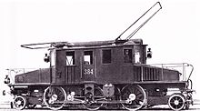
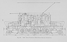
The 6 ft 8 in (2.032 m) driving wheels were unusually large, following the steam locomotive practice with which Darlington Works were more familiar, and the electrical equipment was supplied by Metropolitan-Vickers of Manchester.
The locomotive was heavy for a DC electric and in consideration of its high design speed, four-wheel bogies were used at each end.
When additional locomotives, the EP-3 and then EP-4, were required in the 1930s, these used a (2′C)+(C2′) arrangement, with the carrying axles moved to the ends as twin-axle bogies.
[12] The smaller four-driver 1′B1′ layout was not generally used, but the Swiss narrow-gauge Rhaetian Railway did have one class of seven, the Ge 2/4 in 1912.
Larger and heavier locomotives required more driving wheels, in order to provide enough adhesion whilst limiting axle load.
[iii] The first electric locos to extend the 1′C1′ arrangement to 1′D1′ were the Swiss 440 kilowatts (590 hp) Rhaetian Railway Ge 4/6 class of 1912.
Media related to 1′D1′ locomotives at Wikimedia Commons Electric railways in the US had begun with low-voltage DC systems: 675 V (Baltimore) and 660 V (New York).
Adequate power for main line haulage, even for the slower services through tunnels to the major urban terminuses, required multiple motors.
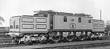
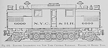
[14] The New York Central S-Motor though was a single rigid frame with four separately driven axles and two leading and trailing trucks.
Once geared and isolated traction motor drives were available, their unsprung weight could also be reduced, encouraging smooth running.
A further advantage for four-motored Do locomotives, rather than the three-motored Co arrangement, is the ease with which the four motors can be switched between series, parallel and series-parallel circuits.
This gave them the possibility to be used as separate 1′Do1′ locomotives at some future time,[18] although this was never needed in practice and they remained coupled until withdrawn in favour of dieselisation in the mid-1950s.
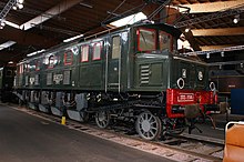
They were followed in 1926 by the two JGR class 7000 [de], later classified as ED54, for Japan, also built by SLM / BBC and with Buchli drives.
With the culture of 1930s Japan and the increasing demand for self-reliance, rather than importing locomotives from overseas, they were used little and were withdrawn in 1948, despite this being the height of Japanese rebuilding post-war.
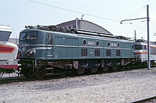
[19] A group of three different trial express passenger locomotives were supplied for the 1,500 V DC Great Indian Peninsula Railway in 1928.
A derivative design was used for the Swiss 'double locomotives' of 1931, built for heavy freight service on the steep gradients of the Gotthard Railway.
A further unpowered carrying axle was also provided, splitting the central Bo group into A1A, which was needed by the extra weight of the transformer for the Swiss low frequency AC system.
Weight saving in the traction motors allowed a return to the (1A)Bo(A1) layout, with the Java bogie and the Winterthur drive and avoiding the central carrying axle.
Both these and the Ae 8/14 had used regenerative braking, useful for descending the Gotthard's steep gradients without overheating and also returning electrical power to the network.
Some aspects of their wartime construction may have reduced their mechanical build quality, leading to high noise levels in the final drives, and a susceptibility to bearing and gear failures, particularly after wheelslip.
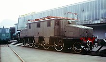
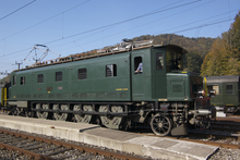
Media related to 2′Do2′ locomotives at Wikimedia Commons The Swiss also used a large four-axle similar to the 2D2 5500, the 2′Do1′ Ae 4/7 (1927–1934).
[v][20] Media related to 2′Do1′ locomotives at Wikimedia Commons Asymmetrical layout had also been used for the Prussian EP 235 [de] for the Silesian Mountain Railway in 1918.