Modular connector
The Federal Communications Commission (FCC) mandated in 1976 an interface registration system, in which they became known as registered jacks.
The convenience of prior existence for designers and ease of use led to a proliferation of modular connectors for many other applications.
Accordingly, various electronic interface specifications exist for applications using modular connectors, which prescribe physical characteristics and assign electrical signals to their contacts.
Registered jack designations describe the signals and wiring used for voice and data communication at customer-facing interfaces of the public switched telephone network (PSTN).
[1] Driven by demand for multiple sets in residences with various lengths of cords, the Bell System introduced customer-connectable part kits and telephones, sold through PhoneCenter stores in the early 1970s.
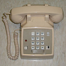
[2] For this purpose, Illinois Bell started installing modular telephone sets on a limited scale in June 1972.
The patents by Edwin C. Hardesty and coworkers, US 3699498 (1972) and US 3860316 (1975), followed by other improvements, were the basis for the modular molded-plastic connectors that became commonplace for telephone cords by the 1980s.
In 1976, these connectors were standardized nationally in the United States by the Registration Interface program of the Federal Communications Commission (FCC), which designated a series of Registered Jack (RJ) specifications for interconnection of customer-premises equipment to the PSTN.
Plugs are used to terminate cables and cords, while jacks are used for fixed locations on surfaces of walls, panels, and equipment.
The connector body positions with omitted or unconnected contacts are unused for the electrical connection but ensure that the plug fits correctly.
For instance, inexpensive telephone cords often have connectors with six positions and four contacts, to which are attached just two wires, carrying only line 1 from a one-, two-, or three-line jack.
When viewed head-on with the retention mechanism on the bottom, jacks will have contact position number 1 on the left and plugs will have it on the right.
For example, a Modified Modular Jack using an offset latching tab was developed by Digital Equipment Corporation to prevent accidental interchange of data and telephone cables.
Excessive resistance may be encountered when inserting an incompatible plug, as the outermost contacts in the jack are forcibly deformed.
The molded plastic bodies of the special plugs may also be colored with a light blueish tinge, to aid in quick recognition.
The crimping tool contains a die that is often exchangeable and is closely matched to the shape and pin count of the modular plug.
The crimper may also permanently deform part of the plastic plug body in such a way that it grips the outer sheath of the cable for secure fastening and strain relief.
The connector provides power to the keyboard on the outer two contacts and receives data signals on the inner pair.
Two of its six possible contact positions connect tip and ring of a single telephone line, and the other two contact positions may be unused, carry a second line, or provide low-voltage power for night light or other features on the telephone set.
However, with German domestic telephone equipment, and that in some neighboring countries, 6P4C plugs and sockets are typically only used to connect the telephone cord to the phone base unit, whereas the mechanically different TAE connector is used at the other end to connect to a service provider interface.
The incompatible T568A and T568B layouts were necessary to preserve the electrical properties of the third and fourth pairs for Ethernet, which operates at much higher frequencies than analog telephony.
An 8P8C modular connection consists of a male plug and a female jack, each with eight equally spaced contacts.
However, the standard un-keyed modular connectors became ubiquitous for computer networking and informally inherited the name RJ45.
For data communication applications (LAN, structured cabling), International Standard IEC 60603 specifies in parts 7-1, 7-2, 7-4, 7-5, and 7-7 not only the same physical dimensions but also high-frequency performance requirements for shielded and unshielded versions of this connector for carrying frequencies up to 100, 250 and 600 MHz.
Although a narrower 4-pin and 6-pin plug fits into the wider 8-pin jack and makes a connection with the available contacts on the plug, because the body of the smaller connector may stress the remaining contacts,[c] the smaller connector can potentially damage the springs of the larger jack.
8P8C connectors are commonly used in computer networking applications, where interconnecting cables are terminated at each end with an 8P8C modular plug wired according to TIA/EIA standards.
Where building network and telephone wiring is pre-installed, the center (blue) pair is often used to carry telephony signals.
[23] This application is common as a console interface for network equipment, such as switches, routers, and headless computers.
In analog mobile telephony, the 8P8C connector was used to connect an AMPS cellular handset to its (separate) base unit; this usage is now obsolete.
An installer can wire the jack to any pin-out or use it as part of a generic structured cabling system such as ISO/IEC 15018 or ISO/IEC 11801 using 8P8C patch panels for both phone and data.