AMES Type 7
The AMES Type 7, also known as the Final GCI, was a ground-based radar system introduced during World War II by the Royal Air Force (RAF).
In a seminal 1939 memo, Robert Hanbury Brown showed that this Dowding system resulted in an inherent inaccuracy of approximately 5 miles (8.0 km), and the only way to reduce this would be to arrange the interception directly from the radar screen.
He suggested spinning the radar antenna and the CRT display to produce a 360 degree picture of the airspace around the station, a concept he referred to as a plan position indicator, or PPI.
When Watt asked him what use radio might be in an air war, Wilkins recalled reading a technical manual a few years earlier that mentioned the effect of aircraft on shortwave signals.
Hugh Dowding, at that time the Air Member for Supply and Organisation in charge of research and development, was intensely interested and demanded a practical demonstration.
[5] This possibility had been raised as early as 1936 in a memo by Henry Tizard, who felt that the Germans would suffer so stiffly at the hands of the RAF that they would turn to night bombing, as they had in World War I.
Once its rough location was determined, an air traffic controller would direct an already airborne night fighter to fly along a line that would intersect the CHL beam at a shallow angle.
While this system worked, it proved extremely time consuming to use, and required careful planning to ensure the fighter arrived in the beam even as the radar operators were moving it to track the target.
[11] A major issue with the Foreness Point system was the large size of the CHL antennas, originally designed by the British Army to track slow-moving ships in the English Channel.
The first Type 8 went into service on Christmas Day 1940 at RAF Sopley, and immediately proved successful, guiding 9 out of 10 test interceptions when the Dowding system was achieving perhaps 1 in 10.
After the Air Officer Commanding-in-Chief Fighter Command expressed his concerns about the delays in the program, a 8 June meeting by the Chain Executive Committee expanded the order once again, this time to thirty-two stations.
[16] A meeting by the Chain Committee on 26 October 1942 about the state of the GCI program revealed that the Mark IV receiver was a source of continuing problems, and that the design of the buildings had not been finalized until September.
[17] Another meeting on 19 December 1942 noted that the original programme was conceived during a period of intense enemy activity, but now it appeared there was no immediate danger of a resumption of night attacks.
"Owing to the acute shortage of manpower, and the need for men in other branches of the Services, as well as the factories, a datum line must be fixed as the safe low limit on which the United Kingdom's night defences can operate."
Window consisted of strips of black paper backed with aluminum foil, cut to the size that made them effective half-wave dipoles for the German radar systems.
The decision to use Window was made and rescinded on several occasions before it was finally allowed when Fighter Command began to receive new radar systems that would not be subject to its effects.
Direction of the night fighters proved almost impossible, both due to the clutter on the screen as well as the returns swamping the IFF Mark III responses on nearby frequencies.
[12] In August 1944 the Air Chief of Staff began developing their post-war plans, which called for Group 11 around London to be maintained largely as-is, while the rest of the country would be reduced to about half the wartime allotment of radars, fighters and anti-aircraft guns.
The topic was revisited and updated several times before being presented to the Prime Minister on 7 July 1945, who immediately rejected it as the entire post-war military had to be considered as a whole, not in isolation.
[25] The government believed another war was at least ten years off, and that the need to reinvigorate the post-war economy meant the minimum possible manpower requirements in the meantime.
As these units also had an improved range of 250 miles (400 km), they eliminated the need for the Master Control Centers, handling interceptions directly from the Type 80's display over an even greater area.
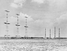
By connecting them in- or out-of-phase, the reception pattern of the array formed several lobes of sensitivity, which could be used to measure the vertical angle of the target with moderate accuracy.
The height-finding system used the reflection of the beam off the ground in front of the site as a secondary signal that mixed with the main lobe, forming a series of sub-beams that were stacked vertically.
[39] This is as opposed to oscilloscope-type displays which typically use faster-acting electrostatic deflection, but requires metal plates inside the tube, which would be difficult to motorize in this fashion.
By comparing the size of the blips from the two selected arrays, the operator could determine which line of shoot the target was closer to, and estimate its vertical angle relative to the station.
[44] The PPI and height finder Intercept Cabins were arranged in a C-shaped pattern on the main floor of the Hall, raised slightly above ground level.
Each Cabin included a PPI and height finder display, a plotting table where the fighter director worked, and a separate recording station for official reporting.
[44] In the open area in the center of the C, sunk into the ground, plotters would take reports called out from the Cabins and place wooden markers on a map to keep track of the battle as a whole.
A second group of plotters received information from the fighter bases and placed similar markers on their own map indicating the location of aircraft outside their own area of operations.
[44] In order to reduce workload, as part of ROTOR the happidromes were further improved with the addition of skiatrons, which directly projected the PPI display onto the map boards.