Amplifier
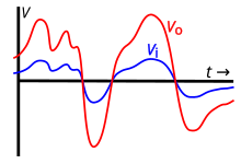
The amount of amplification provided by an amplifier is measured by its gain: the ratio of output voltage, current, or power to input.
In telegraphy, this problem had been solved with intermediate devices at stations that replenished the dissipated energy by operating a signal recorder and transmitter back-to-back, forming a relay, so that a local energy source at each intermediate station powered the next leg of transmission.
Duplex transmission was essential for telephony and the problem was not satisfactorily solved until 1904, when H. E. Shreeve of the American Telephone and Telegraph Company improved existing attempts at constructing a telephone repeater consisting of back-to-back carbon-granule transmitter and electrodynamic receiver pairs.
[6] The Shreeve repeater was first tested on a line between Boston and Amesbury, MA, and more refined devices remained in service for some time.
After the turn of the century it was found that negative resistance mercury lamps could amplify, and were also tried in repeaters, with little success.
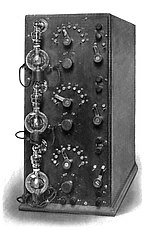
The first practical version of such devices was the Audion triode, invented in 1906 by Lee De Forest,[8][9][10] which led to the first amplifiers around 1912.
[12][13][14][15] The terms amplifier and amplification, derived from the Latin amplificare, (to enlarge or expand),[16] were first used for this new capability around 1915 when triodes became widespread.
[11] It made possible long-distance telephone lines, public address systems, radio broadcasting, talking motion pictures, practical audio recording, radar, television, and the first computers.
They were followed by the invention of the metal–oxide–semiconductor field-effect transistor (MOSFET) by Mohamed M. Atalla and Dawon Kahng at Bell Labs in 1959.
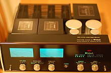
Today, use of vacuum tubes is limited to some high power applications, such as radio transmitters, as well as some musical instrument and high-end audiophile amplifiers.
A small-signal AC test current Ix is applied to the input or output node, all external sources are set to AC zero, and the corresponding alternating voltage Vx across the test current source determines the impedance seen at that node as R = Vx / Ix.
[citation needed] Negative feedback is a technique used in most modern amplifiers to increase bandwidth, reduce distortion, and control gain.
The active device can be a vacuum tube, discrete solid state component, such as a single transistor, or part of an integrated circuit, as in an op-amp.
These nonlinear amplifiers have much higher efficiencies than linear amps, and are used where the power saving justifies the extra complexity.
[28] Traveling wave tube amplifiers (TWTAs) are used for high power amplification at low microwave frequencies.
[29] Klystrons are specialized linear-beam vacuum-devices, designed to provide high power, widely tunable amplification of millimetre and sub-millimetre waves.
Klystrons are designed for large scale operations and despite having a narrower bandwidth than TWTAs, they have the advantage of coherently amplifying a reference signal so its output may be precisely controlled in amplitude, frequency and phase.
[citation needed] Solid-state devices such as silicon short channel MOSFETs like double-diffused metal–oxide–semiconductor (DMOS) FETs, GaAs FETs, SiGe and GaAs heterojunction bipolar transistors/HBTs, HEMTs, IMPATT diodes, and others, are used especially at lower microwave frequencies and power levels on the order of watts specifically in applications like portable RF terminals/cell phones and access points where size and efficiency are the drivers.
New materials like gallium nitride (GaN) or GaN on silicon or on silicon carbide/SiC are emerging in HEMT transistors and applications where improved efficiency, wide bandwidth, operation roughly from few to few tens of GHz with output power of few watts to few hundred of watts are needed.
[32] One set of classifications for amplifiers is based on which device terminal is common to both the input and the output circuit.
All amplifiers are bilateral to some degree; however they may often be modeled as unilateral under operating conditions where feedback is small enough to neglect for most purposes, simplifying analysis (see the common base article for an example).
These functional descriptions usually apply to complete amplifier systems or sub-systems and rarely to individual stages.
Power amplifier circuits (output stages) are classified as A, B, AB and C for analog designs—and class D and E for switching designs.
It features a typical (though substantially simplified) design as found in modern amplifiers, with a class-AB push–pull output stage, and uses some overall negative feedback.
The capacitor allows the AC signal to pass, but blocks the DC bias voltage established by resistors R1 and R2 so that any preceding circuit is not affected by it.
Further circuit elements would probably be found in a real design that would roll-off the frequency response above the needed range to prevent the possibility of unwanted oscillation.
Many modern amplifiers use negative feedback techniques to hold the gain at the desired value and reduce distortion.
Negative loop feedback has the intended effect of lowering the output impedance and thereby increasing electrical damping of loudspeaker motion at and near the resonance frequency of the speaker.
When assessing rated amplifier power output, it is useful to consider the applied load, the signal type (e.g., speech or music), required power output duration (i.e., short-time or continuous), and required dynamic range (e.g., recorded or live audio).
To prevent instability or overheating requires care to ensure solid state amplifiers are adequately loaded.