Analog-to-digital converter
Due to the complexity and the need for precisely matched components, all but the most specialized ADCs are implemented as integrated circuits (ICs).
The SNDR of an ADC is influenced by many factors, including the resolution, linearity and accuracy (how well the quantization levels match the true analog signal), aliasing and jitter.
The input samples are usually stored electronically in binary form within the ADC, so the resolution is usually expressed as the audio bit depth.
Example: In many cases, the useful resolution of a converter is limited by the signal-to-noise ratio (SNR) and other errors in the overall system expressed as an ENOB.
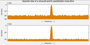
In an oversampled system, noise shaping can be used to further increase SQNR by forcing more quantization error out of band.
Quantization error and (assuming the ADC is intended to be linear) non-linearity are intrinsic to any analog-to-digital conversion.
This will result in additional recorded noise that will reduce the effective number of bits (ENOB) below that predicted by quantization error alone.
[5] For lower bandwidth conversions such as when sampling audio signals at 44.1 kHz, clock jitter has a less significant impact on performance.
To avoid aliasing, the input to an ADC must be low-pass filtered to remove frequencies above half the sampling rate.
Although aliasing in most systems is unwanted, it can be exploited to provide simultaneous down-mixing of a band-limited high-frequency signal (see undersampling and frequency mixer).
[7] For economy, signals are often sampled at the minimum rate required with the result that the quantization error introduced is white noise spread over the whole passband of the converter.
For any ADC the mapping from input voltage to digital output value is not exactly a floor or ceiling function as it should be.
The statistical distribution of the final levels is decided by a weighted average over a region of the range of the ADC.
Resistor-capacitor (RC) circuits have a known voltage charging and discharging curve that can be used to solve for an unknown analog value.
A direct-conversion or flash ADC has a bank of comparators sampling the input signal in parallel, each firing for a specific voltage range.
The comparator bank feeds a digital encoder logic circuit that generates a binary number on the output lines for each voltage range.
A successive-approximation ADC uses a comparator and a binary search to successively narrow a range that contains the input voltage.
A special advantage of the ramp-compare system is that converting a second signal just requires another comparator and another register to store the timer value.
Delta converters have very wide ranges and high resolution, but the conversion time is dependent on the input signal behavior, though it will always have a guaranteed worst-case.
Some converters combine the delta and successive approximation approaches; this works especially well when high frequency components of the input signal are known to be small in magnitude.
By combining the merits of the successive approximation and flash ADCs this type is fast, has a high resolution, and can be implemented efficiently.
In practice, the individual differences between the M ADCs degrade the overall performance reducing the spurious-free dynamic range (SFDR).
The two parts of the ADC may be widely separated, with the frequency signal passed through an opto-isolator or transmitted wirelessly.
Such ADCs were once the most popular way to show a digital display of the status of a remote analog sensor.
Although the term ADC is usually associated with measurement of an analog voltage, some partially-electronic devices that convert some measurable physical analog quantity into a digital number can also be considered ADCs, for instance: In many cases, the most expensive part of an integrated circuit is the pins, because they make the package larger, and each pin has to be connected to the integrated circuit's silicon.
Analog-to-digital converters are integral to modern music reproduction technology and digital audio workstation-based sound recording.
Digital storage oscilloscopes need very fast analog-to-digital converters, also crucial for software-defined radio and their new applications.
Many sensors in scientific instruments produce an analog signal; temperature, pressure, pH, light intensity etc.
Flat-panel displays are inherently digital and need an ADC to process an analog signal such as composite or VGA.
Testing an analog-to-digital converter requires an analog input source and hardware to send control signals and capture digital data output.