Beam (structure)
Beams are characterized by their manner of support, profile (shape of cross-section), equilibrium conditions, length, and material.
The loads carried by a beam are transferred to columns, walls, or girders, then to adjacent structural compression members, and eventually to the ground.
It measures not only the total area of the beam section, but the square of each patch's distance from the axis.
Then, when the concrete has cured, the tendons are slowly released and the beam is immediately under eccentric axial loads.
This eccentric loading creates an internal moment, and, in turn, increases the moment-carrying capacity of the beam.
For beams that are not slender a different theory needs to be adopted to account for the deformation due to shear forces and, in dynamic cases, the rotary inertia.
The beam formulation adopted here is that of Timoshenko and comparative examples can be found in NAFEMS Benchmark Challenge Number 7.
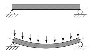
Engineers are interested in determining deflections because the beam may be in direct contact with a brittle material such as glass.
A stiffer beam (high modulus of elasticity and/or one of higher second moment of area) creates less deflection.
Other shapes, like L-beam (angles), C (channels), T-beam and double-T or tubes, are also used in construction when there are special requirements.
This system provides horizontal bracing for small trenches, ensuring the secure installation of utilities.