Bending (metalworking)
Bending is a manufacturing process that produces a V-shape, U-shape, or channel shape along a straight axis in ductile materials, most commonly sheet metal.
[1] There are three basic types of bending on a press brake, each is defined by the relationship of the end tool position to the thickness of the material.
A die with a long rail form tool with a radiused tip that locates the inside profile of the bend is called a punch.
Punches are usually attached to the ram of the machine by clamps and move to produce the bending force.
The other types of bending listed use specially designed tools or machines to perform the work.
[2] A disadvantage of air bending is that, because the sheet does not stay in full contact with the dies, it is not as precise as some other methods, and stroke depth must be kept very accurate.
Variations in the thickness of the material and wear on the tools can result in defects in parts produced.
Springback depends on material properties, influencing the resulting bend angle.
[2] The flexibility and relatively low tonnage required by air bending are helping to make it a popular choice.
A disadvantage is that a different tool set is needed for each bend angle, sheet thickness, and material.
Three-point bending is a newer process that uses a die with an adjustable-height bottom tool, moved by a servo motor.
Adjustments between the ram and the upper tool are made using a hydraulic cushion, which accommodates deviations in sheet thickness.
[2] This method will typically bottom or coin the material to set the edge to help overcome springback.
This bending method is typically considered a "non-marking" forming process suitable to pre-painted or easily marred surfaces.
The roll bending process induces a curve into bar or plate workpieces.
Using a special punch called a radius ruler with relieved areas on the urethane U-bends greater than 180° can be achieved in one hit, something that is not possible with conventional press tooling.
Urethane tooling should be considered a consumable item and while they are not cheap, they are a fraction of the cost of dedicated steel.
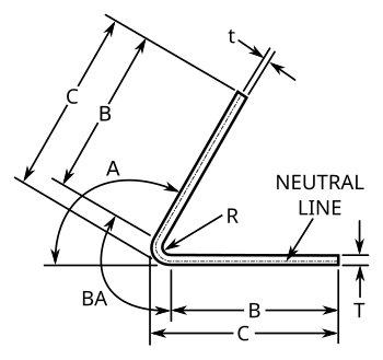
All formulas use the following keys: The neutral line (also called the Neutral axis) is an imaginary profile that can be drawn through a cross-section of the workpiece that represents the locus where no tensile or compressive stress are present but shear stresses are at their maximum.
Most 3D Solid Modeling CAD software has sheet metal functions or add-ons that performs these calculations automatically.
The outside set back (OSSB) is the length from the tangent point of the radius to the apex of the outside of the bend.
BD is calculated using the following formula, where A is the angle in radians (=degrees*π/180):[11] For bends at 90 degrees this formula can be simplified to: K-factor is a ratio of the location of the neutral line to the material thickness as defined by t/T where t = location of the neutral line and T = material thickness.
The K-factor formula does not take the forming stresses into account but is simply a geometric calculation of the location of the neutral line after the forces are applied and is thus the roll-up of all the unknown (error) factors for a given setup.
The K-factor depends on many variables including the material, the type of bending operation (coining, bottoming, air-bending, etc.)
The following equation relates the K-factor to the bend allowance:[12] The following table is a "rule of thumb".
For instance, differences in spring-back have a direct influence on the resulting bend angle.