Bending
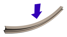
In applied mechanics, bending (also known as flexure) characterizes the behavior of a slender structural element subjected to an external load applied perpendicularly to a longitudinal axis of the element.
The structural element is assumed to be such that at least one of its dimensions is a small fraction, typically 1/10 or less, of the other two.
[1] When the length is considerably longer than the width and the thickness, the element is called a beam.
A large diameter, but thin-walled, short tube supported at its ends and loaded laterally is an example of a shell experiencing bending.
A beam deforms and stresses develop inside it when a transverse load is applied on it.
In the quasi-static case, the amount of bending deflection and the stresses that develop are assumed not to change over time.
The stress distribution in a beam can be predicted quite accurately when some simplifying assumptions are used.
[1] In the Euler–Bernoulli theory of slender beams, a major assumption is that 'plane sections remain plane'.
For stresses that exceed yield, refer to article plastic bending.
At yield, the maximum stress experienced in the section (at the furthest points from the neutral axis of the beam) is defined as the flexural strength.
If, in addition, the beam is homogeneous along its length as well, and not tapered (i.e. constant cross section), and deflects under an applied transverse load
The maximum compressive stress is found at the uppermost edge of the beam while the maximum tensile stress is located at the lower edge of the beam.
Because of this area with no stress and the adjacent areas with low stress, using uniform cross section beams in bending is not a particularly efficient means of supporting a load as it does not use the full capacity of the beam until it is on the brink of collapse.
Wide-flange beams (Ɪ-beams) and truss girders effectively address this inefficiency as they minimize the amount of material in this under-stressed region.
are the coordinates of a point on the cross section at which the stress is to be determined as shown to the right,
Using this equation it is possible to calculate the bending stress at any point on the beam cross section regardless of moment orientation or cross-sectional shape.
For large deformations of the body, the stress in the cross-section is calculated using an extended version of this formula.
) close to 0.3, the shear correction factor for a rectangular cross-section is approximately The rotation (
) are given by According to Euler–Bernoulli, Timoshenko or other bending theories, the beams on elastic foundations can be explained.
In some applications such as rail tracks, foundation of buildings and machines, ships on water, roots of plants etc., the beam subjected to loads is supported on continuous elastic foundations (i.e. the continuous reactions due to external loading is distributed along the length of the beam)[8][9][10][11] The dynamic bending of beams,[12] also known as flexural vibrations of beams, was first investigated by Daniel Bernoulli in the late 18th century.
Bernoulli's equation of motion of a vibrating beam tended to overestimate the natural frequencies of beams and was improved marginally by Rayleigh in 1877 by the addition of a mid-plane rotation.
In 1921 Stephen Timoshenko improved the theory further by incorporating the effect of shear on the dynamic response of bending beams.
The Euler-Bernoulli and Timoshenko theories for the dynamic bending of beams continue to be used widely by engineers.
The Euler–Bernoulli equation for the dynamic bending of slender, isotropic, homogeneous beams of constant cross-section under an applied transverse load
Timoshenko improved upon that theory in 1922 by adding the effect of shear into the beam equation.
Shear deformations of the normal to the mid-surface of the beam are allowed in the Timoshenko–Rayleigh theory.
The equation for the bending of a linear elastic, isotropic, homogeneous beam of constant cross-section under these assumptions is[7][13] where
) close to 0.3, the shear correction factor are approximately For free, harmonic vibrations the Timoshenko–Rayleigh equations take the form This equation can be solved by noting that all the derivatives of
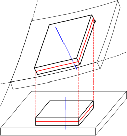
There are several theories that attempt to describe the deformation and stress in a plate under applied loads two of which have been used widely.
In terms of displacements, the equilibrium equations for an isotropic, linear elastic plate in the absence of external load can be written as In direct tensor notation, The special assumption of this theory is that normals to the mid-surface remain straight and inextensible but not necessarily normal to the mid-surface after deformation.