Weather radar
Raw images are routinely processed by specialized software to make short term forecasts of future positions and intensities of rain, snow, hail, and other weather phenomena.
[2][3] Marshall and his doctoral student Walter Palmer are well known for their work on the drop size distribution in mid-latitude rain that led to understanding of the Z-R relation, which correlates a given radar reflectivity with the rate at which rainwater is falling.
In the United Kingdom, research continued to study the radar echo patterns and weather elements such as stratiform rain and convective clouds, and experiments were done to evaluate the potential of different wavelengths from 1 to 10 centimeters.
In 1953 Donald Staggs, an electrical engineer working for the Illinois State Water Survey, made the first recorded radar observation of a "hook echo" associated with a tornadic thunderstorm.
He convinced the bureau staff to let him broadcast live from their office and asked a meteorologist to draw him a rough outline of the Gulf of Mexico on a transparent sheet of plastic.
During the broadcast, he held that transparent overlay over the computer's black-and-white radar display to give his audience a sense both of Carla's size and of the location of the storm's eye.
Meanwhile, rapid advances in computer technology led to algorithms to detect signs of severe weather, and many applications for media outlets and researchers.
[13][14] Weather radars send directional pulses of microwave radiation, on the order of one microsecond long, using a cavity magnetron or klystron tube connected by a waveguide to a parabolic antenna.
The wavelengths of 1 – 10 cm are approximately ten times the diameter of the droplets or ice particles of interest, because Rayleigh scattering occurs at these frequencies.
This formula assumes the beam is symmetrically circular, "r" is much greater than "h" so "r" taken at the beginning or at the end of the pulse is almost the same, and the shape of the volume is a cone frustum of depth "h".
The length of this phase is determined by the need for the microwave radiation (which travels at the speed of light) to propagate from the detector to the weather target and back again, a distance which could be several hundred kilometers.
The horizontal distance from station to target is calculated simply from the amount of time that elapses from the initiation of the pulse to the detection of the return signal.
[25] Over the area covered by radar echoes, a program assigns a precipitation type according to the surface temperature and dew point reported at the underlying weather stations.
This causes the water molecule dipole to be oriented in that direction; so, radar beams are, generally, polarized horizontally in order to receive the maximal signal reflection.
These signals can be compared in several useful ways:[27][28] With more information about particle shape, dual-polarization radars can more easily distinguish airborne debris from precipitation, making it easier to locate tornados.
[12] In 2004, ARMOR Doppler Weather Radar in Huntsville, Alabama was equipped with a SIGMET Antenna Mounted Receiver, giving Dual-Polarmetric capabilities to the operator.
CAPPIs call for a large number of angles from near the horizontal to near the vertical of the radar to have a cut that is as close as possible at all distance to the height needed.
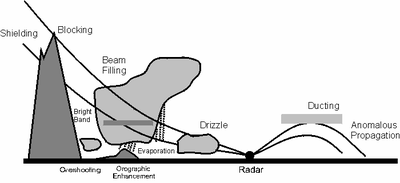
[44][45]Radar data interpretation depends on many hypotheses about the atmosphere and the weather targets, including:[46] These assumptions are not always met; one must be able to differentiate between reliable and dubious echoes.
[46] This type of false return is relatively easy to spot on a time loop if it is due to night cooling or marine inversion as one sees very strong echoes developing over an area, spreading in size laterally but not moving and varying greatly in intensity.
Not only the coarser resolution of the radar blur the image but the sounding incorporates area that are echo free, thus extending the thunderstorm beyond its real boundaries.
This leads to underestimation of the precipitation rate at larger distances and fools the user into thinking that rain is lighter as it moves away.The radar beam has a distribution of energy similar to the diffraction pattern of a light passing through a slit.
To compensate for this behaviour, radar sites are often chosen to somewhat overlap in coverage to give different points of view of the same storms if one is experiencing attenuation.
Due to the spread of dual-polarization radar systems, robust and efficient approaches for the compensation of rain attenuation are currently implemented by operational weather services.
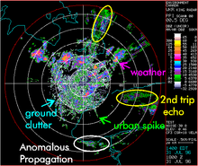
Since rain and snow clouds are usually moving, Doppler velocities can be used to eliminate a good part of the clutter (ground echoes, reflections from buildings seen as urban spikes, anomalous propagation).
Polarization offers a direct typing of the echoes which could be used to filter more false data or produce separate images for specialized purposes, such as clutter, birds, etc.
A program by the Center for Collaborative Adaptive Sensing of the Atmosphere (CASA) aims to supplement the regular NEXRAD (a network in the United States) using many low cost X-band (3 cm) weather radar mounted on cellular telephone towers.
The attenuation is significant due to the wavelength used but each point in the coverage area is seen by many radars, each viewing from a different direction and compensating for data lost from others.
To mitigate the different demands, scanning strategies have been developed according to the type of radar, the wavelength used and the most common weather situations in the area considered.
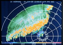
The red-green feature at the upper left is the motion of clouds near the radar itself, and a signature of falling meteorites is inside the yellow ellipse at image center.
Furthermore, the meteorites cause local wind turbulence, which is noticeable on Doppler outputs, and fall nearly vertically so their resting place on the ground is close to their radar signature.