Ceramic matrix composite
To increase the crack resistance or fracture toughness, particles (so-called monocrystalline whiskers or platelets) were embedded into the matrix.
[6] The reason for this property of SiC fibers is that most of them contain additional elements like oxygen, titanium and/or aluminum yielding a tensile strength above 3 GPa.
These enhanced elastic properties are required for various three-dimensional fiber arrangements (see example in figure) in textile fabrication, where a small bending radius is essential.
Under defined condition this gas mixture deposits fine and crystalline silicon carbide on the hot surface within the preform.
[8][9] This CVI procedure leaves a body with a porosity of about 10–15%, as access of reactants to the interior of the preform is increasingly blocked by deposition on the exterior.
A strong bond would require a very high elongation capability of the fiber bridging the crack and would result in a brittle fracture, as with conventional ceramics.
The production of CMC material with high crack resistance requires a step to weaken this bond between the fibers and matrix.
In fracture mechanics, the measured data (force, geometry and crack surface) are normalized to yield the so-called stress intensity factor (SIF), KIc.
Compared to the sample of conventional SiSiC ceramic, two observations can be made: In the table, CVI, LPI, and LSI denote the manufacturing process of the C/SiC-material.
Since the Young's modulus of the load-carrying fibers is generally lower than that of the matrix, the slope of the curve decreases with increasing load.
The compressive strengths shown in the table are lower than those of conventional ceramics, where values above 2000 MPa are common; this is a result of porosity.
The Poisson's ratio shows an anomaly when measured perpendicular to the plane of the fabric because interlaminar cracks increase the sample thickness.
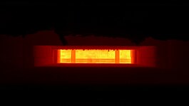
The application of CMCs in brake disks demonstrates the effectiveness of ceramic composite materials under extreme thermal shock conditions.
The broad spectrum of manufacturing techniques with different sintering additives, mixtures, glass phases, and porosities are crucial for the results of corrosion tests.
Amorphous glass and silica phases at the grain boundaries determine the speed of corrosion in concentrated acids and bases and result in creep at high temperatures.
Temperatures above about 1,600 °C (2,910 °F) and a low partial pressure of oxygen result in so-called active oxidation, in which CO, CO2 and gaseous SiO are formed causing rapid loss of SiC.
CMC materials overcome the major disadvantages of conventional technical ceramics, namely brittle failure and low fracture toughness, and limited thermal shock resistance.
[26] These include: In addition to the foregoing, CMCs can be used in applications which employ conventional ceramics or in which metal components have limited lifetimes due to corrosion or high temperatures.
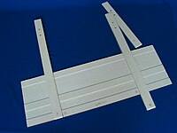
Several follow-up programs focused on the development, manufacture, and qualification of nose cap, leading edges and steering flaps for the NASA X-38 space vehicle.
For industrial applications in a hot gas environment, though, several hundred cycles of thermal loads and up to many thousands of hours of lifetime are required.
Developed by Thales Alenia Space, the IXV was scheduled to make its first flight in 2014 on the fourth Vega mission (VV04) over the Gulf of Guinea.
The thermal protection system for the underside of the vehicle, comprising the nose, leading edges and lower surface of the wing, were designed and made by Herakles[32] using a ceramic matrix composite (CMC), carbon/silicon-carbide (C/SiC), in this case based on the liquid silicon infilration (LSI) process (see manufacturing procedures above).
[33] The European Commission funded a research project, C3HARME, under the NMP-19-2015 call of Framework Programmes for Research and Technological Development (H2020) in 2016 for the design, development, production, and testing of a new class of ultra-high temperature ceramic matrix composites (UHTCMC) reinforced with silicon carbide fibers and carbon fibers suitable for applications in severe aerospace environments such as propulsion and Thermal protection systems (TPSs).
Chemical vapor deposition can apply coatings on a laid-able fiber tape in large quantities and GE managed to infiltrate and cast parts with very high silicon densities, higher than 90% for cyclic fatigue environments, thanks to thermal processing.
Currently, research is being done to combat common failure modes such as delamination, erosion, and cracking caused by steam or molten deposits.
Delamination and cracking due to molten deposits are typically caused by the reaction with the EBC creating an unexpected microstructure leading to CTE mismatch and low toughness in that phase.
Overall benefits of EBCs:[citation needed] Oxygen-containing gas at temperatures above 1,000 °C (1,800 °F) is rather corrosive for metal and silicon carbide components.
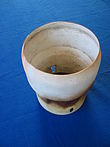
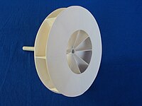
[citation needed] Conventional SiC, or sometimes the less expensive SiSiC, have been used successfully for more than 25 years in slide or journal bearings of pumps.
Under compressive stress, the ceramic static bearing has a low risk of failure, but a SiC shaft sleeve does not have this situation and must, therefore, have a large wall thickness and/or be specially designed.
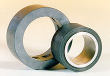
[48] A hydrostatic bearing system (see picture) has survived several hours at a speed up to 10,000 revolutions per minute, various loads, and 50 cycles of start/stop transients without any significant traces of wear.


Legend: SiSiC: conventional SiSiC , SiCSiC(CVI) and CSiC(CVI): SiC/SiC and C/SiC manufactured in CVI processes, CSiC(95) und CSiC(93): C/SiC manufactured by the LPI-method, Ox(PP): oxide ceramic composite, CSiC(Si): C/SiC manufactured via the LSI process.