Universal joint
It consists of a pair of hinges located close together, oriented at 90° to each other, connected by a cross shaft.
[1] U-joints are also sometimes called by various eponymous names, as follows: The main concept of the universal joint is based on the design of gimbals, which have been in use since antiquity.
One anticipation of the universal joint was its use by the ancient Greeks on ballistae.
[3] The mechanism was later described in Technica curiosa sive mirabilia artis (1664) by Gaspar Schott, who mistakenly claimed that it was a constant-velocity joint.
[4][5][6] Shortly afterward, between 1667 and 1675, Robert Hooke analysed the joint and found that its speed of rotation was nonuniform, but that property could be used to track the motion of the shadow on the face of a sundial.
[4] In fact, the component of the equation of time which accounts for the tilt of the equatorial plane relative to the ecliptic is entirely analogous to the mathematical description of the universal joint.
The first recorded use of the term 'universal joint' for this device was by Hooke in 1676, in his book Helioscopes.
[7][8][9] He published a description in 1678,[10] resulting in the use of the term Hooke's joint in the English-speaking world.
In 1841, the English scientist Robert Willis analyzed the motion of the universal joint.
[12] By 1845, the French engineer and mathematician Jean-Victor Poncelet had analyzed the movement of the universal joint using spherical trigonometry.
Edmund Morewood's 1844 patent for a metal coating machine called for a universal joint, by that name, to accommodate small alignment errors between the engine and rolling mill shafts.
[15] Charles Amidon used a much smaller universal joint in his bit-brace patented 1884.
[16] Beauchamp Tower's spherical, rotary, high speed steam engine used an adaptation of the universal joint c. 1885.
[17] The term 'Cardan joint' appears to be a latecomer to the English language.
Examples include an 1868 report on the Exposition Universelle of 1867[18] and an article on the dynamometer translated from French in 1881.
The Cardan joint suffers from one major problem: even when the input drive shaft axle rotates at a constant speed, the output drive shaft axle rotates at a variable speed, thus causing vibration and wear.
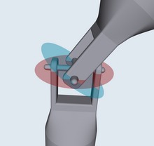
Also shown are a set of fixed coordinate axes with unit vectors
However, axle 1 attaches to the gimbal at the red points on the red plane of rotation in the diagram, and axle 2 attaches at the blue points on the blue plane.
Coordinate systems fixed with respect to the rotating axles are defined as having their x-axis unit vectors (
is confined to the "blue plane" in the diagram and is the result of the unit vector on the x axis
is not unique since the arctangent function is multivalued, however it is required that the solution for
A configuration known as a double Cardan joint drive shaft partially overcomes the problem of jerky rotation.
These tend to bend them in a direction perpendicular to the common plane of the shafts.
This applies forces to the support bearings and can cause "launch shudder" in rear wheel drive vehicles.
[20] The intermediate shaft will also have a sinusoidal component to its angular velocity, which contributes to vibration and stresses.
are the angles for the input and output of the universal joint connecting the drive and the intermediate shafts respectively, and
NOTE: The reference for measuring angles of input and output shafts of universal joint are mutually perpendicular axes.
So, in absolute sense the forks of the intermediate shaft are parallel to each other.
A double Cardan joint consists of two universal joints mounted back to back with a centre yoke; the centre yoke replaces the intermediate shaft.
A Thompson coupling is a refined version of the double Cardan joint.